
Replacement
- Make
- Rover
- Model
- 600 Rover 600 Repair Manual - Volumes 1 and 2 - 2nd Edition
- Section
- Interior fittings › Replacement
BodyReplacement
Replacement
►: 7
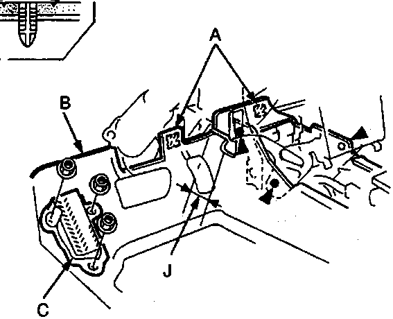
- Fasteners
- Carpet
- Foot rest
- Door sill moulding
- Carpet
- Retainer
- Carpet
- Slit
- Wire tie
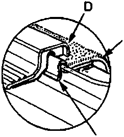
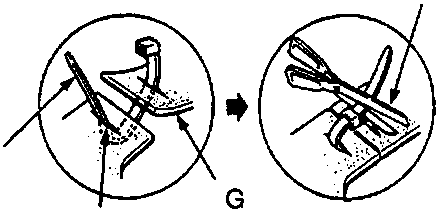
- Clip locations and quantities shown by black triangles.
- Cut the area marked ‘J’ first, then pull the carpet back as shown.
- Cut off as illustrated at position ‘K’.
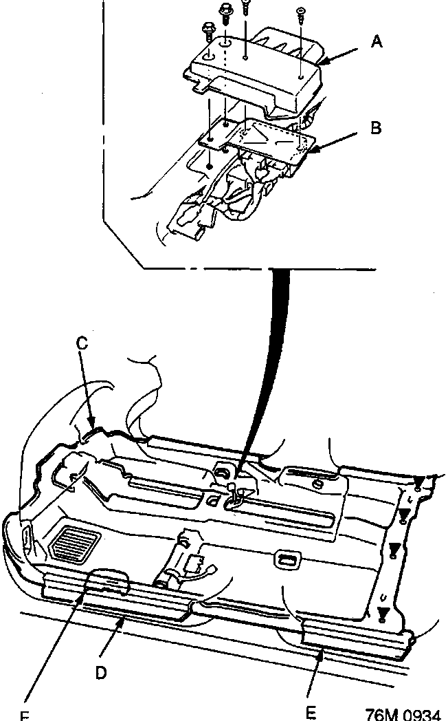
- Unit cover
- Control unit
- Carpet
- Front door sill moulding
- Rear door sill moulding
- Opener cover
- Remove:
- Front seats
- Rear seat cushion
- Centre consoles
- Front seat belt lower anchor bolts
- Centre pillar lower trim
- Right and left kick panels
- Door sill mouldings
- Foot rest and opener cover
- Control unit
Parts & tools for this job For Rover 600
- TOOLTrim removal tool kitSearch: trim removal tool kit
- PARTTouch-up paintSearch: Rover touch up paint
- PARTPanel clip assortmentSearch: Rover panel clips assortment
Links open Amazon search results in a new tab. As an Amazon Associate I earn from qualifying purchases.