
Front View (page 3 of 3)
- Make
- Rover
- Model
- 600 Rover 600 Repair Manual - Volumes 1 and 2 - 2nd Edition
- Section
- Wire harness and earth locations
ElectricalFront View · page 3 of 3
Note: The ABS fuse/relay box is on the right side of the engine compartment.
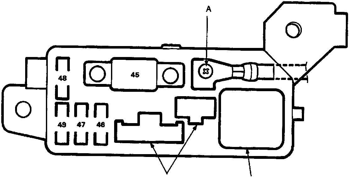
A To battery
B To ABS motor relay
C To main wire harness
| Fuse Number | Amps | Wire Colour | Circuit(s) and Component(s) Protected |
|---|---|---|---|
| 45 | 50A | - | ABS motor relay |
| 46 | 15A | WHT/GRN | ABS control unit (+ B1) |
| 47 | 15A | WHT | ABS control unit (+ B2) |
| 48 | 15A | WHT/BLK | ABS control unit (+ B3) |
| 49 | 7.5A | WHT/BLU | ABS control unit |
Parts & tools for this job For Rover 600
- TOOLDigital multimeterSearch: automotive digital multimeter
- PARTAssorted fuse kitSearch: car fuse assortment kit
- TOOLWire crimper and connector kitSearch: wire crimper connector kit
Links open Amazon search results in a new tab. As an Amazon Associate I earn from qualifying purchases.