
Refit
- Make
- Rover
- Model
- Coupé, Cabriolet & Tourer 200/400 Coupé, Cabriolet & Tourer Workshop Manual
- Section
- Doors › Refit
BodyRefit
Service Repair No. 86.25.39
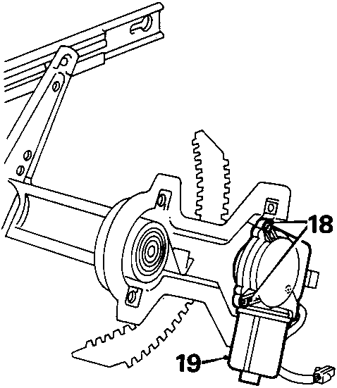
- Drill out 3 rivets, motor to regulator.
- Remove motor from regulator.
Refit
- Position motor to regulator, fit rivets and peen over ends.
- Position regulator to door and align fixings.
- Fit bolts to secure regulator, tighten bolts to 6 Nm.
- Align regulator top slide to door and fit bolts, do not tighten.
- Operate regulator to align top slide and tighten bolts to 6 Nm.
- Enter glass into door, align glass to regulator.
- Fit bolts to regulator and align glass.
- Tighten bolts glass to regulator 6 Nm.
- Align front glass channel to glass.
- Fit bolt glass channel to door.
- Motor window up or down to align glass channel.
- Tighten bolt front glass channel to door 6 Nm.
- Fit plastic sheet to door and secure sheet edges to door.
- Connect door lock multiplug and secure harness clips to door.
- Fit arm rest support bracket and tighten screws.
- Fit window lift control unit and connect multiplugs.
- Fit screws control unit to door, tighten screws.
- Connect Lucars, position speaker to door and tighten screws.
- Fit door trim pad, see Front door trim pad.
Remove
- Remove door trim pad, see Front door trim pad.
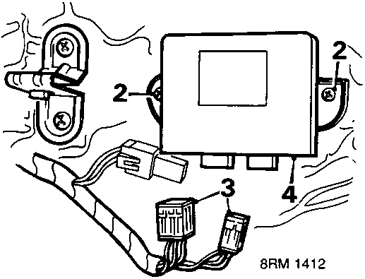
- Remove 2 screws, control unit to door.
- Disconnect 2 multiplugs from control unit.
- Remove control unit.
Refit
- Connect multiplugs to control unit.
- Fit control unit to door and tighten screws.
- Fit door trim pad, see Front door trim pad.
Parts & tools for this job For Rover Coupé, Cabriolet & Tourer
- TOOLTrim removal tool kitSearch: trim removal tool kit
- PARTTouch-up paintSearch: Rover touch up paint
- PARTPanel clip assortmentSearch: Rover panel clips assortment
Links open Amazon search results in a new tab. As an Amazon Associate I earn from qualifying purchases.