
Remove
- Make
- Rover
- Model
- Coupé, Cabriolet & Tourer 200/400 Coupé, Cabriolet & Tourer Workshop Manual
- Section
- Doors › Remove
BodyRemove
Service Repair No. Door latch 76.37.12
Service Repair No. Motor 86.26.08
Remove
- Fully close window.
- Remove door trim pad, see Front door trim pad.
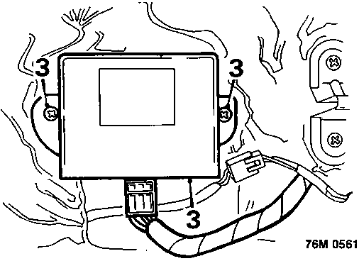
- 4 and 5 door models – if fitted: Remove 2 screws securing window control unit and move unit aside.
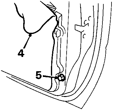
- Release plastic sheet from rear of door.
- Not Coupe and Cabriolet: Remove screw securing lower end of window rear guide channel to door.
- Cabriolet: Remove 2 screws securing window rear guide channel, remove channel.
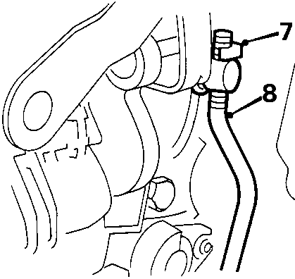
- Raise exterior handle and release clip securing link rod to outside handle mechanism.
- Release link rod from outside handle.
Note: Take care not to disturb setting of threaded link rod.
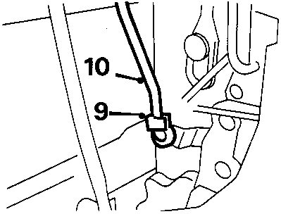
- Release clip securing private lock link rod to door latch.
- Release link rod from door latch.
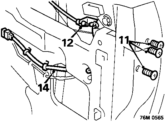
- Remove 3 screws and release latch from door.
- Release clip securing interior handle link rod or cable to door latch.
Coupe: Release cable from abutment bracket. - Release interior handle link from door latch.
- Central locking: Disconnect lock motor fly – lead; release multiplug and fly – lead clips from door.
Parts & tools for this job For Rover Coupé, Cabriolet & Tourer
- TOOLTrim removal tool kitSearch: trim removal tool kit
- PARTTouch-up paintSearch: Rover touch up paint
- PARTPanel clip assortmentSearch: Rover panel clips assortment
Links open Amazon search results in a new tab. As an Amazon Associate I earn from qualifying purchases.