
Ball joint - upper - steering knuckle
- Make
- Land Rover
- Model
- Discovery II (UK)
- Section
- Repairs › Ball joint - upper - steering knuckle
Front suspensionBall joint - upper - steering knuckle
Ball joint - upper - steering knuckle
$% 60.15.02
CAUTION: Each ball joint can be replaced up to three times before the axle yoke bore becomes oversize. Before commencing work, thoroughly clean surface of joint and check for yellow paint marks approx. 12 mm (0.5 in) wide. If 3 marks are found, the axle case must be renewed.
Remove
- Remove steering knuckle. FRONT SUSPENSION, REPAIRS, Steering knuckle.
- Support the chassis on stands.
- Support the front axle on stands.
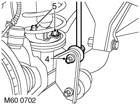
- Fit tool
- Fit tool
- Fit tool
- Remove 2 nuts securing anti-roll bar lower links 13. Press upper ball joint from axle. When ram lead to front axle, use a 16 mm spanner to prevent link joint from turning.
- Remove 2 bolts securing each front damper to axle.
- Remove 8 bolts securing chassis crossmember 14. Dismantle the tools. and remove crossmember.
- Remove bolt securing brake hose and ABS Refit sensor harness bracket to axle.
- Lower the front axle, release front spring from damper and remove front spring.
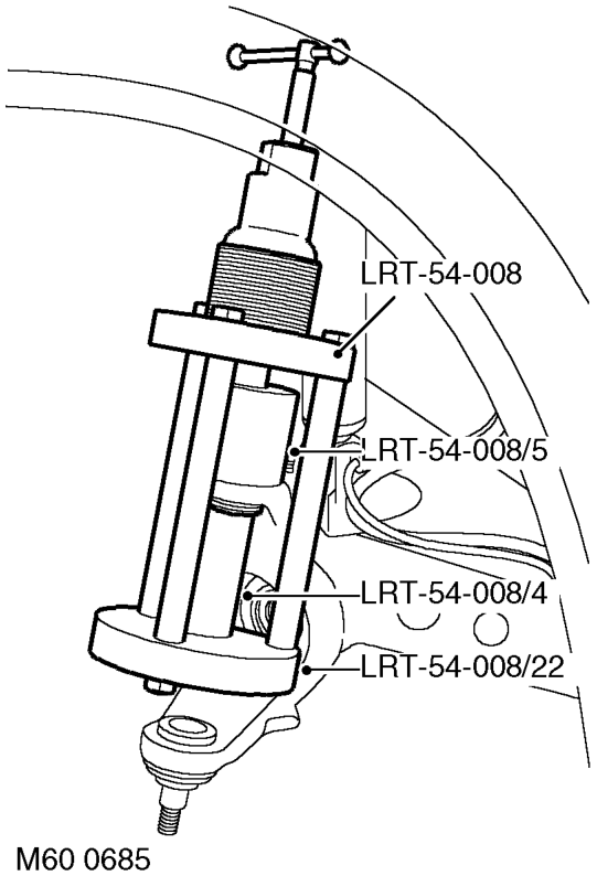
- Fit tool LRT-54-008/22 to tool LRT-54-008. LRT-54-008/4 to tool LRT-54-008, and secure with screw. LRT-54-008 with all attachments to upper ball joint.. LRT-54-008/5 to the top of the ball joint.
screw reaches the end of its stroke, retract the lead screw and screw the ram further into the tool. Repeat the operation until the ball joint is released from the axle.
- Clean upper ball joint location and surrounding area of axle yoke.
- Apply a 12 mm (0.5 in) wide yellow paint stripe on axle yoke, adjacent to upper ball joint location.
Parts & tools for this job For Land Rover Discovery
- TOOLTie rod end toolSearch: tie rod end puller
- TOOLBall joint separatorSearch: ball joint separator
- FLUIDPower steering fluidSearch: Land Rover power steering fluid
Links open Amazon search results in a new tab. As an Amazon Associate I earn from qualifying purchases.