
Reassembly (page 2 of 2)
- Make
- Land Rover
- Model
- Discovery II (UK)
- Section
- Overhaul
Manual gearbox - R380Reassembly · page 2 of 2
- Fit layshaft bearing track to front cover.
- Using tool LRT-99-002 and a suitable mandrel, fit pilot bearing outer track to input shaft.
- Clean synchroniser hubs, gears and bearings.
- Position output shaft in protected vice jaws, output end upwards.
- Fit 2nd gear bearing, 2nd gear and synchromesh baulk rings onto output shaft.
- Position 1st / 2nd synchroniser hub onto output shaft. Ensure that baulk rings are correctly located in hub.
- Position 1st gear synchromesh baulk rings, needle roller bearing, 1st gear and bearing collar onto output shaft. Ensure baulk rings are correctly located in hub.
- Using a feeler gauge, check end float of 2nd
- Remove output shaft from vice.
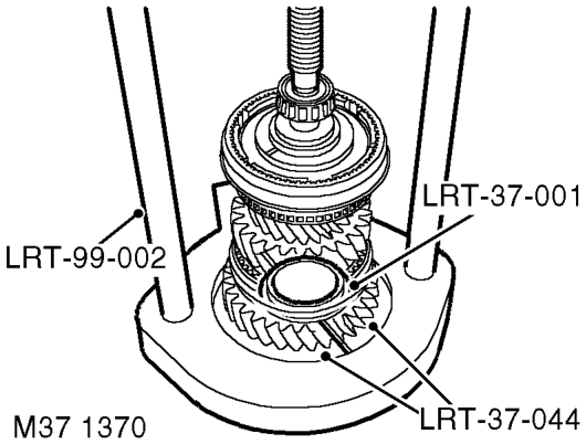
- Invert output shaft in vise and fit 3rd gear,
- Remove output shaft from vice.
- Using tool LRT-37-001, LRT-37-044 and LRT-99-002, press taper bearing onto output shaft.
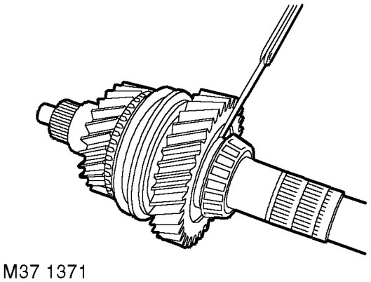
- Using a feeler gauge, check end float of 1st gear between gear and collar flange: l New = 0.05 - 0.20 mm (0.002 - 0.008 in) 19. Using tool l Service limit = 0.327 mm (0.012 in)
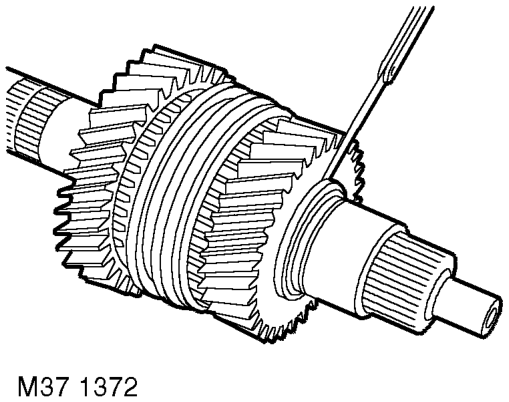
gear between gear and output shaft flange: l New = = 0.04 - 0.21 mm (0.0016 - 0.0083 in) l Service limit = 0.337 mm (0.013 in)
bearing, baulk rings, 3rd / 4th synchroniser and spacer.
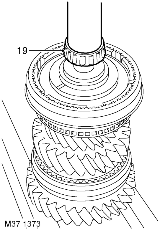
LRT-99-002 and a suitable mandrel, press pilot bearing onto output shaft.
Parts & tools for this job For Land Rover Discovery
- PARTClutch kitSearch: Land Rover Discovery clutch kit
- TOOLClutch alignment toolSearch: clutch alignment tool
- FLUIDGear oilSearch: Land Rover Discovery manual gearbox oil
Links open Amazon search results in a new tab. As an Amazon Associate I earn from qualifying purchases.