
ABS hydraulic modulator - ’d’ series 97.5my on (page 2 of 2)
- Make
- Rover
- Model
- 400 Workshop Manual
- Year
- 1995–2000
- Section
- Repairs
BrakesABS hydraulic modulator - ’d’ series 97.5my on · page 2 of 2
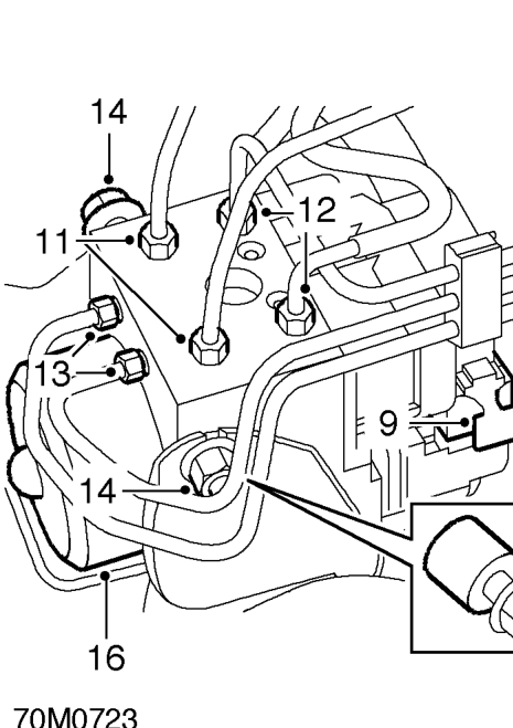
- Pull clip outwards and disconnect multiplug from modulator ECU.
- Position cloth under modulator to absorb fluid spillage.
CAUTION: Do not allow brake fluid to contact paint finished surfaces as paint may be damaged. If spilled, remove fluid and clean area with clean warm water.
- Disconnect 2 inlet brake pipe unions master cylinder and from top of modulator. Remove brake pipes.
CAUTION: Plug the connections.
- Disconnect 2 front outlet brake pipe unions from top of modulator.
CAUTION: Plug the connections.
- Disconnect 2 rear outlet brake pipe unions from front of modulator.
CAUTION: Plug the connections.
- Loosen 2 nuts securing modulator to mounting bracket.
- Release modulator lower bush from mounting bracket spigot.
- Extract ABS modulator from mounting bracket.
Do not carry out further dismantling if component is removed for access only.
- Remove mounting rubber assembly from each side of modulator and mounting rubber from underneath.
- Fit parts to new modulator.
Refit
- Engage spigot and fit modulator to mounting bracket and tighten mounting nuts to 21 Nm.
- Connect brake pipe unions to modulator, ensuring pipes are connected to their correct ports: MC 1 = Master cylinder primary MC 2 = Master cylinder secondary RF = Right hand front LF = Left hand front RR = Right hand rear LR = Left hand rear
- Tighten unions to 14 Nm.
- Connect multiplug to modulator and press clip in fully to secure.
- Fit air intake hose to air cleaner.
- Connect air intake hose to throttle housing and secure with clip.
- Connect multiplug to MAP sensor and secure harness to air intake hose clip.
- Secure hoses to air intake hose clips.
- Connect breather pipe to air intake hose and secure with clip.
- Bleed brakes. See Adjustments.
- Connect battery earth lead.
- To ensure correct operation, the system MUST be tested using TestBook.
Parts & tools for this job For 1995 Rover 400
- TOOLOBD2 scanner with ABSSearch: OBD2 scanner ABS SRS
- TOOLDigital multimeterSearch: automotive digital multimeter
Links open Amazon search results in a new tab. As an Amazon Associate I earn from qualifying purchases.