
Manually adjustable (page 2 of 2)
- Make
- Rover
- Model
- 600 Rover 600 Repair Manual - Volumes 1 and 2 - 2nd Edition
- Section
- Interior fittings
BodyManually adjustable · page 2 of 2
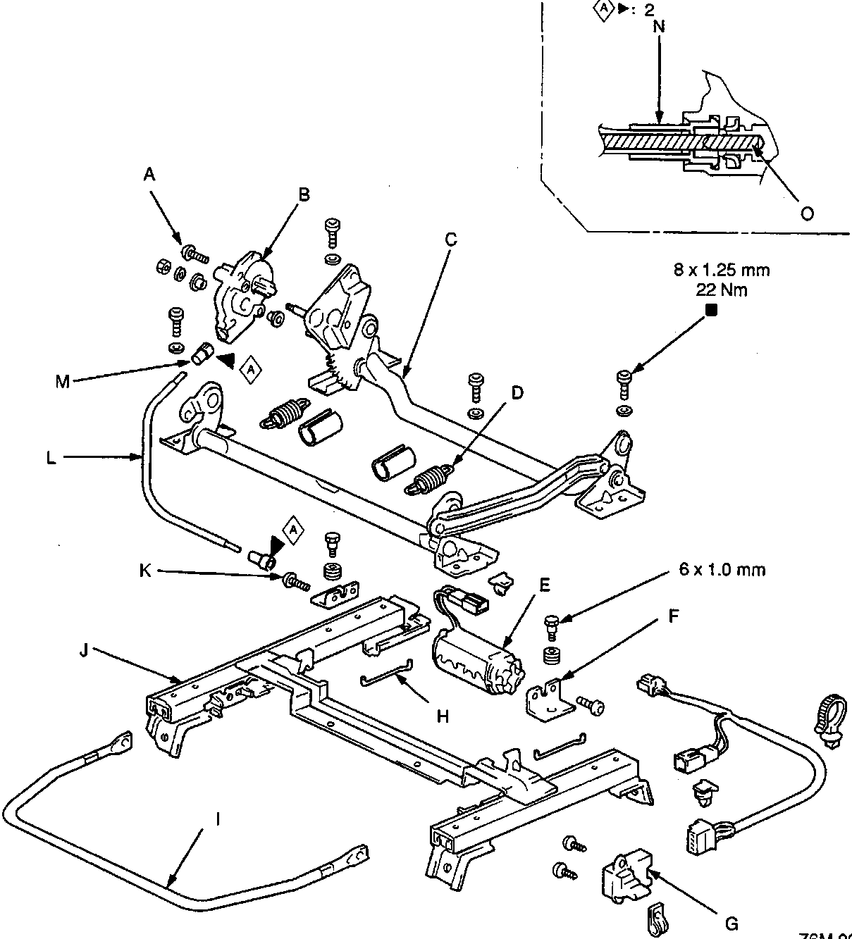
- Screw
- Reductor
- Elevation adjuster
- Spring
- Motor
- Motor support bracket
- Power height switch
- Lock spring
- Lever
- Seat track
- Screw
- Joint cable
- Cable connector
- Cable connector
- Inner cable
- Cable connector locations and quantities are shown by black triangles.
- Use TORX T20 at items A and K.
- Use TORX T40 where indicated by a black square.
Note:
• Apply grease (aeroshell grease 6) to the moving surface.
• Check the slide and height operations.
Note 2: Take care not to bend the joint cable and make sure the cable connector is connected properly.
- Installation is the reverse of the removal procedure.
Parts & tools for this job For Rover 600
- TOOLTrim removal tool kitSearch: trim removal tool kit
- PARTTouch-up paintSearch: Rover touch up paint
- PARTPanel clip assortmentSearch: Rover panel clips assortment
Links open Amazon search results in a new tab. As an Amazon Associate I earn from qualifying purchases.