
Adjustment
- Make
- Rover
- Model
- 600 Rover 600 Repair Manual - Volumes 1 and 2 - 2nd Edition
- Section
- Doors › Adjustment
BodyAdjustment
Adjustment
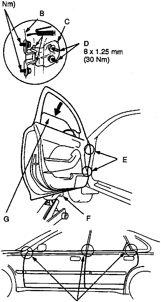
30 Nm
- A Door mounting bolts
- B Door
- C Hinge
- D Hinge mounting bolts
- E Hinges
- F Cloth
- Loosen the door mounting bolts (A) slightly to move the door IN or OUT until it is flush with the body. If necessary, you can install a shim behind one hinge to make the door edges PARALLEL with the body.
- Loosen the hinge mounting bolts (D), and move the door BACKWARD or FORWARD, UP or DOWN as necessary to equalise the gaps.
Note: Place the vehicle on a firm, level surface when adjusting the doors.
- After installing the door, check for a flush fit with the body, then check for equal gap between the front, rear, and bottom door edges and the body.
The door and body edges should also be parallel. Adjust at the hinges as shown.
CAUTION: Place a cloth on the jack to prevent damage to the door when loosening the door and hinge mounting bolts for adjustment.
Note: Check for water leaks.
- Lower the glass at position 'G'.
- The door and body edges at position 'H' should be parallel.
Parts & tools for this job For Rover 600
- TOOLTrim removal tool kitSearch: trim removal tool kit
- PARTTouch-up paintSearch: Rover touch up paint
- PARTPanel clip assortmentSearch: Rover panel clips assortment
Links open Amazon search results in a new tab. As an Amazon Associate I earn from qualifying purchases.