
Latch
- Make
- Rover
- Model
- 600 Rover 600 Repair Manual - Volumes 1 and 2 - 2nd Edition
- Section
- Doors › Latch
BodyLatch
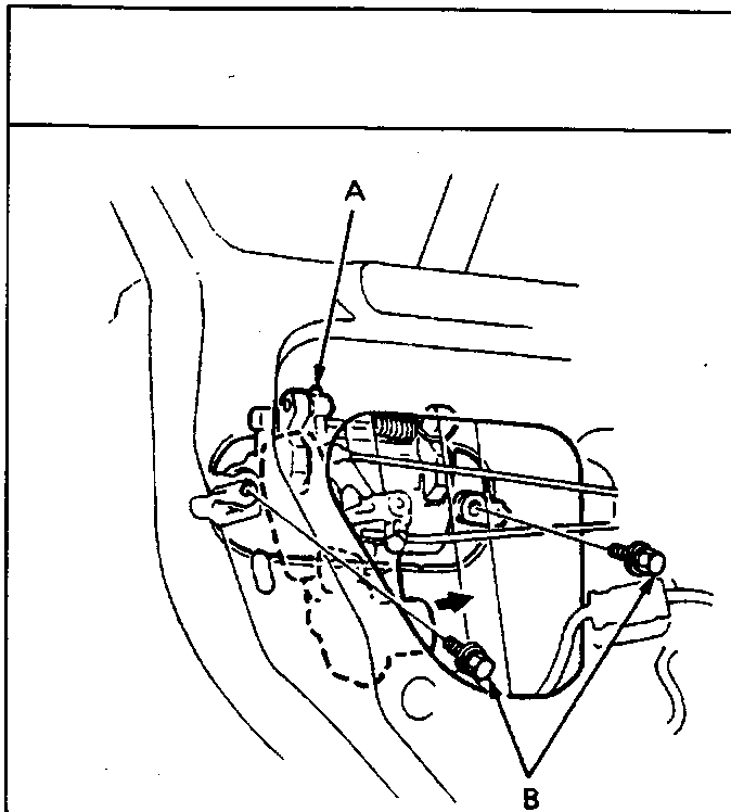
- Move the rear channel and latch, then remove the outer handle bolts.
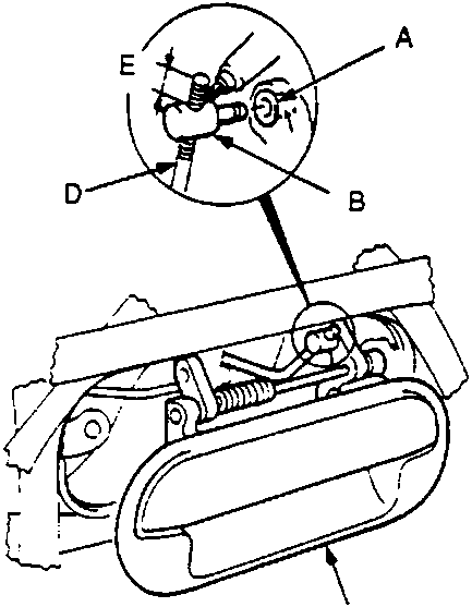
- Pull out the outer handle.
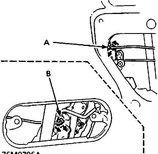
- Raise the glass fully.
- Remove:
- Door panel
- Plastic cover
- Outer handle
- Disconnect the inner handle rod and lock rod.
Note: To ease reassembly, note the location (E) of the outer handle rod on the joint before disconnecting it.
- Installation is the reverse of the removal procedure.
- Check the door lock operation.
LATCH
Replacement
Prise the outer handle rod out of its joint using a flat-bladed screwdriver.
Parts & tools for this job For Rover 600
- TOOLTrim removal tool kitSearch: trim removal tool kit
- PARTTouch-up paintSearch: Rover touch up paint
- PARTPanel clip assortmentSearch: Rover panel clips assortment
Links open Amazon search results in a new tab. As an Amazon Associate I earn from qualifying purchases.