
Glass height
- Make
- Rover
- Model
- 600 Rover 600 Repair Manual - Volumes 1 and 2 - 2nd Edition
- Section
- Doors › Glass height
BodyGlass height
GLASS HEIGHT
Adjustment
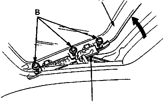
- A Glass
- B Screws
- C Glass bracket
The roof panel should be even with the glass weatherstrip, to within 1 ± 0.5 mm (0.04 ± 0.02 in) all the way around. If not, slide the sunshade back, and:
- Tilt-up the glass.
- Loosen the screws and adjust the glass.
- Repeat on opposite side if necessary.
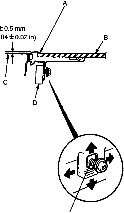
- A Glass weatherstrip
- B Glass
- C Roof panel
- D Glass bracket
- Apply liquid thread lock to the screw at position 'E'
- Side-to-side fit of glass weatherstrip can be adjusted by loosening the frame bolts and moving the frame right or left by hand.
Parts & tools for this job For Rover 600
- TOOLTrim removal tool kitSearch: trim removal tool kit
- PARTTouch-up paintSearch: Rover touch up paint
- PARTPanel clip assortmentSearch: Rover panel clips assortment
Links open Amazon search results in a new tab. As an Amazon Associate I earn from qualifying purchases.