
Adjustment
- Make
- Rover
- Model
- 600 Rover 600 Repair Manual - Volumes 1 and 2 - 2nd Edition
- Section
- Doors › Adjustment
BodyAdjustment
Adjustment
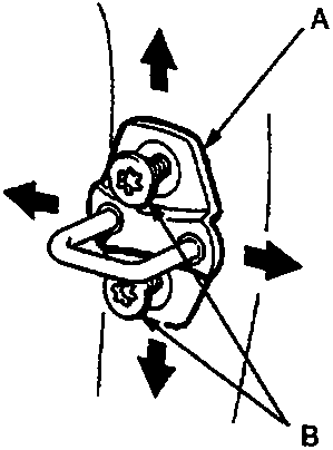
8 x 1.25 mm
(18 Nm)
- A Striker
- B Screws
Make sure the door latches securely without slamming. If it requires adjustment:
- Draw a line around the striker for reference.
- Loosen the screws and move the striker IN and OUT to adjust the way the door fits in the aperture. Move the striker UP or DOWN to align it with the latch opening. Then lightly tighten the screws and recheck.
Note: Hold the outer handle out and push the door against the body to ensure that the striker allows a flush fit.
- If the door latches properly, tighten the screws and recheck.
Parts & tools for this job For Rover 600
- TOOLTrim removal tool kitSearch: trim removal tool kit
- PARTTouch-up paintSearch: Rover touch up paint
- PARTPanel clip assortmentSearch: Rover panel clips assortment
Links open Amazon search results in a new tab. As an Amazon Associate I earn from qualifying purchases.