
Component Location
- Make
- Rover
- Model
- 600 Rover 600 Repair Manual - Volumes 1 and 2 - 2nd Edition
- Section
- Doors › Component Location
BodyComponent Location · page 1 of 2
Component Location
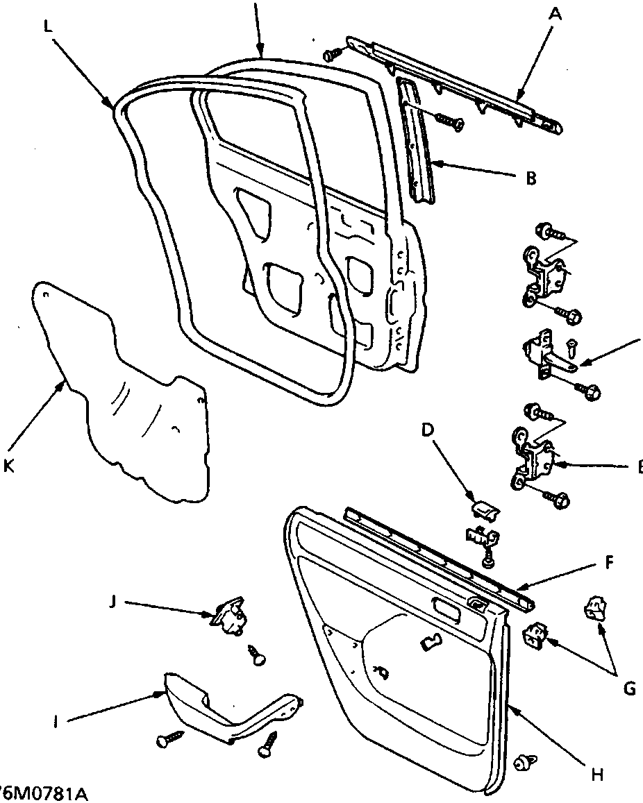
| A | Outer moulding | I | Armrest |
| B | Sash garnish | J | Power window switch |
| C | Detent rod | K | Plastic cover |
| D | Lock knob trim | L | Weatherstrip |
| E | Hinge | M | Door |
| F | Inner moulding | ||
| G | Screw grommets | ||
| H | Door panel |
Parts & tools for this job For Rover 600
- TOOLTrim removal tool kitSearch: trim removal tool kit
- PARTTouch-up paintSearch: Rover touch up paint
- PARTPanel clip assortmentSearch: Rover panel clips assortment
Links open Amazon search results in a new tab. As an Amazon Associate I earn from qualifying purchases.