
Replacement
- Make
- Rover
- Model
- 600 Rover 600 Repair Manual - Volumes 1 and 2 - 2nd Edition
- Section
- Doors › Replacement
BodyReplacement
Replacement
Note:
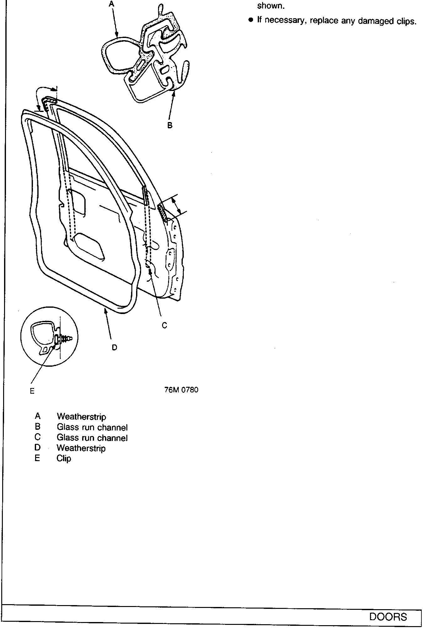
- Before installing the weatherstrip, apply clear sealant to the shadowed areas of the door as shown.
- If necessary, replace any damaged clips.
- A Weatherstrip
- B Glass run channel
- C Glass run channel
- D Weatherstrip
- E Clip
Parts & tools for this job For Rover 600
- TOOLTrim removal tool kitSearch: trim removal tool kit
- PARTTouch-up paintSearch: Rover touch up paint
- PARTPanel clip assortmentSearch: Rover panel clips assortment
Links open Amazon search results in a new tab. As an Amazon Associate I earn from qualifying purchases.