
Replacement
- Make
- Rover
- Model
- 600 Rover 600 Repair Manual - Volumes 1 and 2 - 2nd Edition
- Section
- Doors › Replacement
BodyReplacement
Replacement
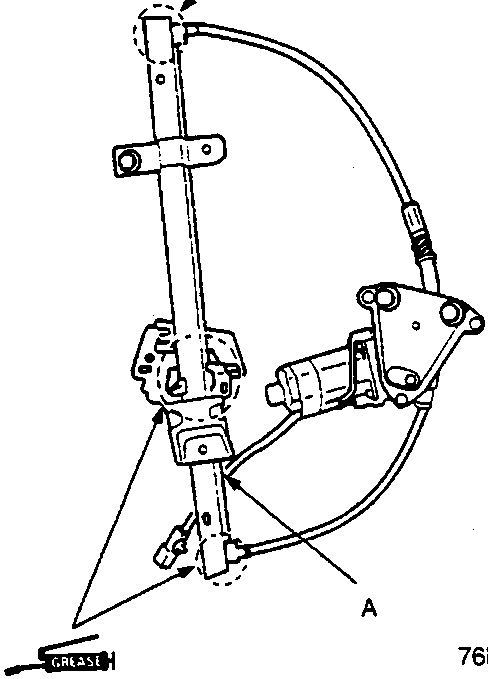
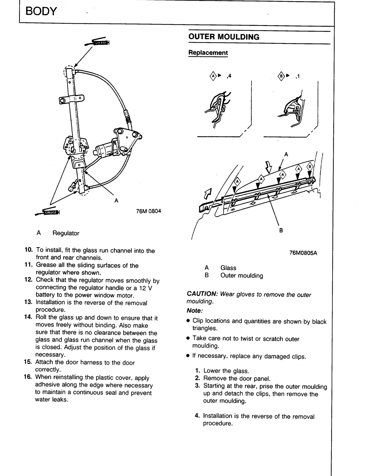
- To install, fit the glass run channel into the front and rear channels.
- Grease all the sliding surfaces of the regulator where shown.
- Check that the regulator moves smoothly by connecting the regulator handle or a 12 V battery to the power window motor.
- Installation is the reverse of the removal procedure.
- Roll the glass up and down to ensure that it moves freely without binding. Also make sure that there is no clearance between the glass and glass run channel when the glass is closed. Adjust the position of the glass if necessary.
- Attach the door harness to the door correctly.
- When reinstalling the plastic cover, apply adhesive along the edge where necessary to maintain a continuous seal and prevent water leaks.
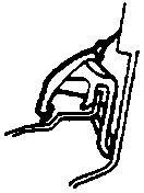
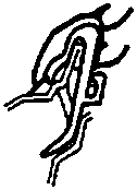
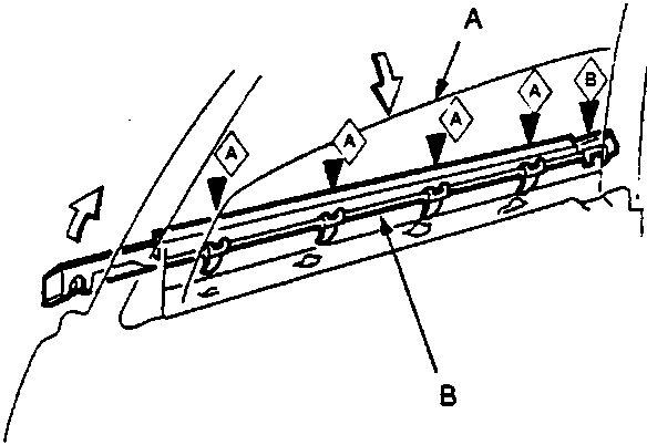
CAUTION: Wear gloves to remove the outer moulding.
Note:
- Clip locations and quantities are shown by black triangles.
- Take care not to twist or scratch outer moulding.
- If necessary, replace any damaged clips.
- Lower the glass.
- Remove the door panel.
- Starting at the rear, prise the outer moulding up and detach the clips, then remove the outer moulding.
- Installation is the reverse of the removal procedure.
Original page
Parts & tools for this job For Rover 600
- TOOLTrim removal tool kitSearch: trim removal tool kit
- PARTTouch-up paintSearch: Rover touch up paint
- PARTPanel clip assortmentSearch: Rover panel clips assortment
Links open Amazon search results in a new tab. As an Amazon Associate I earn from qualifying purchases.