
Glass/regulator (page 2 of 2)
- Make
- Rover
- Model
- 600 Rover 600 Repair Manual - Volumes 1 and 2 - 2nd Edition
- Section
- Doors
BodyGlass/regulator · page 2 of 2
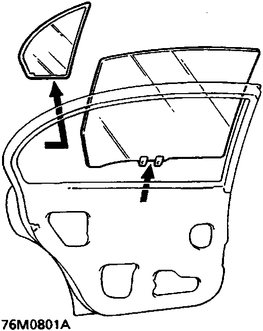
- Remove the sixth light glass by sliding the glass with its seal forward.
- Carefully pull the glass out through the window aperture.
Note: Take care not to drop the glass inside the door.
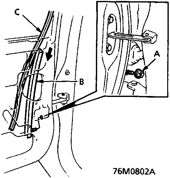
A Nut
B Centre channel
C Glass run channel
8. Peel the glass run channel and remove the nut, then remove the centre channel.
▶: 4
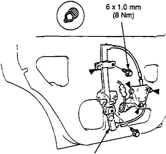
A Regulator
Note:
- Bolt locations and quantities are shown by black triangles.
- Remove the two bolts and loosen the four bolts. Disconnect the connector (power window model). Take out the regulator through the hole in the door.
Parts & tools for this job For Rover 600
- TOOLTrim removal tool kitSearch: trim removal tool kit
- PARTTouch-up paintSearch: Rover touch up paint
- PARTPanel clip assortmentSearch: Rover panel clips assortment
Links open Amazon search results in a new tab. As an Amazon Associate I earn from qualifying purchases.