
Alignment
- Make
- Rover
- Model
- 600 Rover 600 Repair Manual - Volumes 1 and 2 - 2nd Edition
- Section
- Exterior fittings › Alignment
BodyAlignment
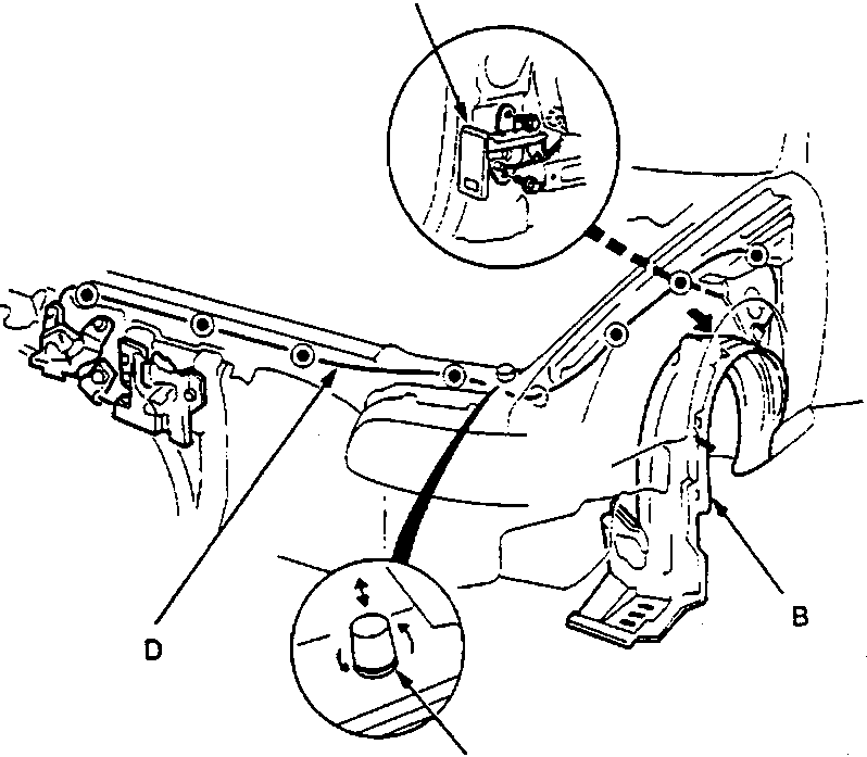
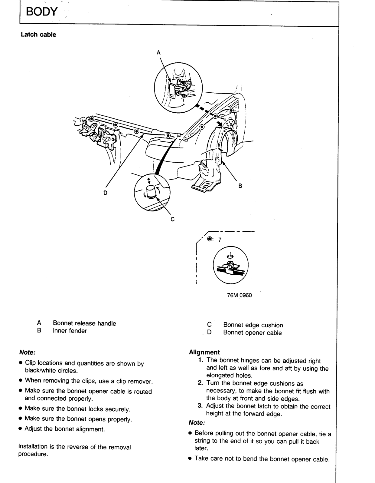
76M 0960
| A Bonnet release handle | C Bonnet edge cushion |
| B Inner fender | D Bonnet opener cable |
Note:
- Clip locations and quantities are shown by black/white circles.
- When removing the clips, use a clip remover.
- Make sure the bonnet opener cable is routed and connected properly.
- Make sure the bonnet locks securely.
- Make sure the bonnet opens properly.
- Adjust the bonnet alignment.
Installation is the reverse of the removal procedure.
Alignment
- The bonnet hinges can be adjusted right and left as well as fore and aft by using the elongated holes.
- Turn the bonnet edge cushions as necessary, to make the bonnet fit flush with the body at front and side edges.
- Adjust the bonnet latch to obtain the correct height at the forward edge.
Note:
- Before pulling out the bonnet opener cable, tie a string to the end of it so you can pull it back later.
- Take care not to bend the bonnet opener cable.
Original page
Parts & tools for this job For Rover 600
- TOOLTie rod end toolSearch: tie rod end puller
- TOOLBall joint separatorSearch: ball joint separator
- FLUIDPower steering fluidSearch: Rover power steering fluid
Links open Amazon search results in a new tab. As an Amazon Associate I earn from qualifying purchases.