
Power door mirror
- Make
- Rover
- Model
- 600 Rover 600 Repair Manual - Volumes 1 and 2 - 2nd Edition
- Section
- Exterior fittings › Power door mirror
BodyPower door mirror
POWER DOOR MIRROR
Replacement
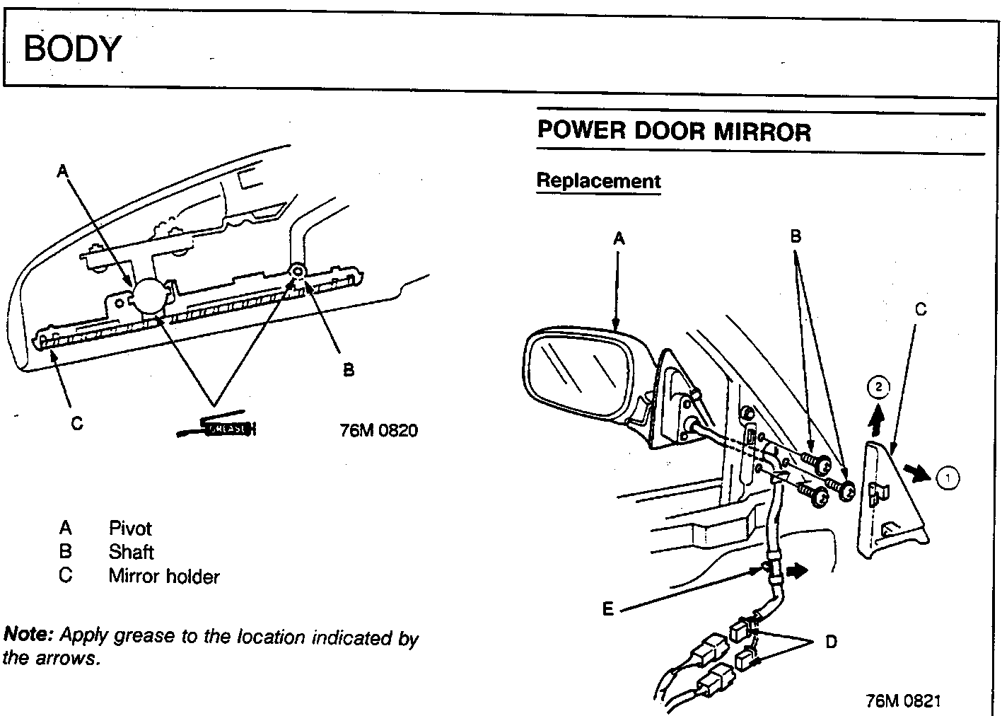
Note: Apply grease to the location indicated by the arrows.
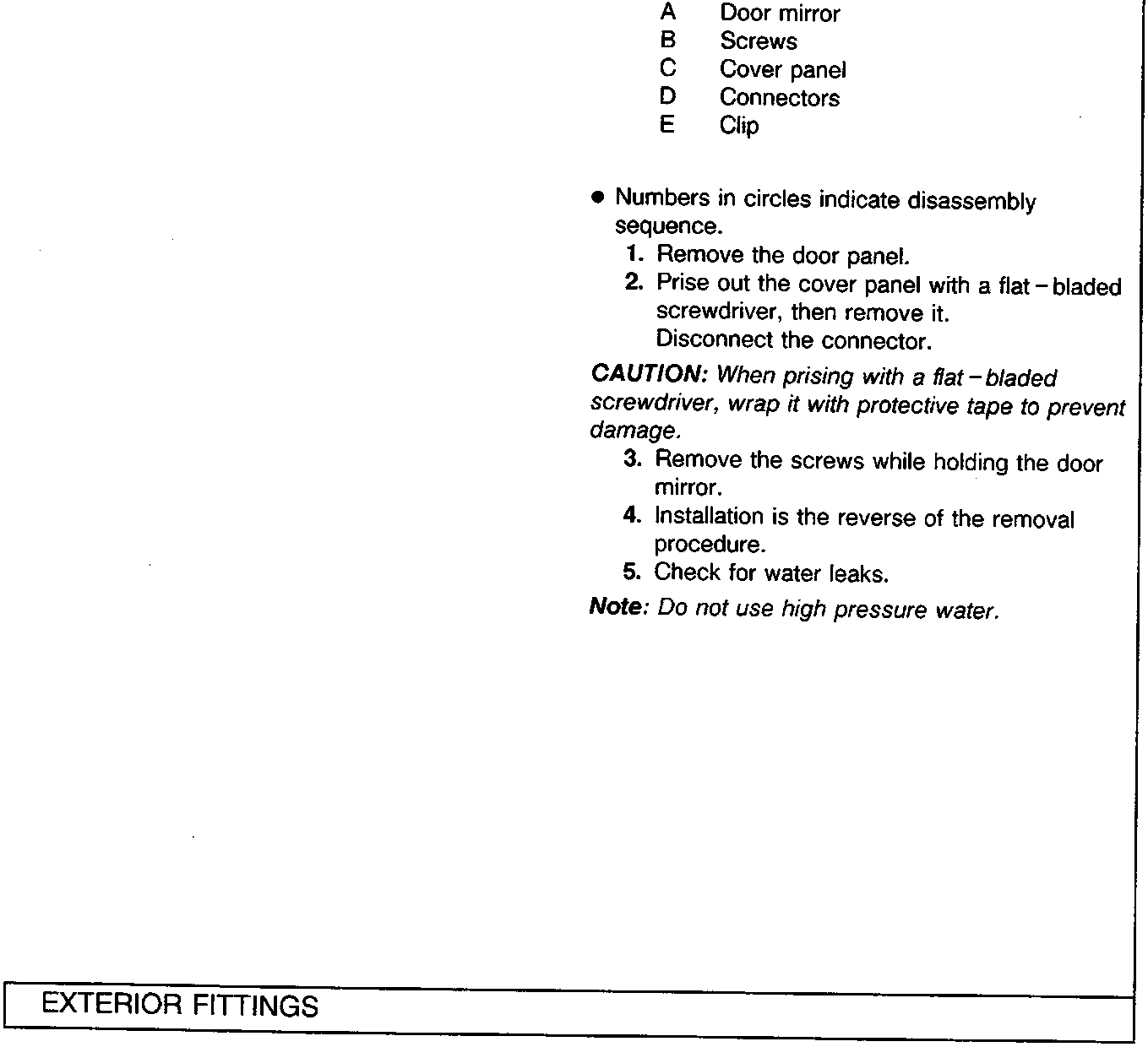
- Numbers in circles indicate disassembly sequence.
- Remove the door panel.
- Prise out the cover panel with a flat – bladed screwdriver, then remove it. Disconnect the connector.
CAUTION: When prising with a flat – bladed screwdriver, wrap it with protective tape to prevent damage.
- Remove the screws while holding the door mirror.
- Installation is the reverse of the removal procedure.
- Check for water leaks.
Note: Do not use high pressure water.
Parts & tools for this job For Rover 600
- TOOLTrim removal tool kitSearch: trim removal tool kit
- PARTTouch-up paintSearch: Rover touch up paint
- PARTPanel clip assortmentSearch: Rover panel clips assortment
Links open Amazon search results in a new tab. As an Amazon Associate I earn from qualifying purchases.