
Equipment
- Make
- Rover
- Model
- 600 Rover 600 Repair Manual - Volumes 1 and 2 - 2nd Edition
- Section
- Exterior fittings › Equipment
Equipment
Note: Removal and installation of a rear screen requires the following equipment.
Windscreen repair kit (BHM 705) comprising of:
- P.U adhesive cartridge
- Spirit wipe
- Body primer
- Glass primer
- Cotton bud applicators
- Cutting (piano) wire
2 Lower (L shaped) spacers.
8 Spacer blocks.
Sealer applicator gun.
Suction cup lifters.
Sharp knife (to trim off old bonding material).
Awl (to make a hole through existing adhesive for cutting wire).
Leak test equipment.
Masking tape.
WARNING: When working with solvents and primers use PVC gloves and protective clothing. Always use protective gloves when handling glass.
Removal
CAUTION: Use wing covers, seat covers, etc. to avoid damaging any surfaces.
Do not damage the heated rear screen elements.
- To remove the rear screen first remove the following :
- Rear seat back rest.
- Rear pillar trim panels.
- Rear parcel shelf.
- Rear interior light.
- Disconnect heated rear screen wires.
- Lower the rear edge of headlining and protect with tape, taking care not to bend the headlining excessively.
- Lower the boot, apply a protective covering i.e, masking tape to front edge of boot, screen pillars, edges of wings and rear edge of roof to protect the paintwork.
- Remove the moulding lower holder and clips, then remove the side mouldings (detaching the clips from the retainers), then remove both the side mouldings and upper moulding as shown.
Moulding lower holder removal
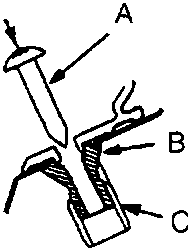
- A Screw
- B Screw grommet
- C Lower holder
76M1063
- Remove or loosen the screw.
- Place the screw in the grommet again (do not screw it in) and press it down.
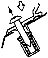
76M1064
- Pull the screw with the moulding lower holder out of the body.
Note: Replace any damaged clips as necessary.
Parts & tools for this job For Rover 600
- TOOLTrim removal tool kitSearch: trim removal tool kit
- PARTTouch-up paintSearch: Rover touch up paint
- PARTPanel clip assortmentSearch: Rover panel clips assortment
Links open Amazon search results in a new tab. As an Amazon Associate I earn from qualifying purchases.