
Original page
- Make
- Rover
- Model
- 600 Rover 600 Repair Manual - Volumes 1 and 2 - 2nd Edition
- Section
- Exterior fittings › Original page
BodyOriginal page · page 1 of 3
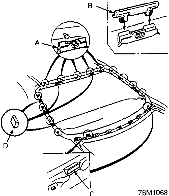
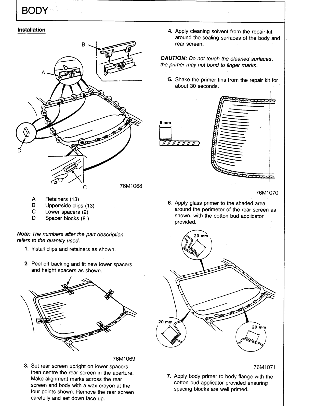
- A Retainers (13)
- B Upper/side clips (13)
- C Lower spacers (2)
- D Spacer blocks (8 )
Note: The numbers after the part description refers to the quantity used.
- Install clips and retainers as shown.
- Peel off backing and fit new lower spacers and height spacers as shown.
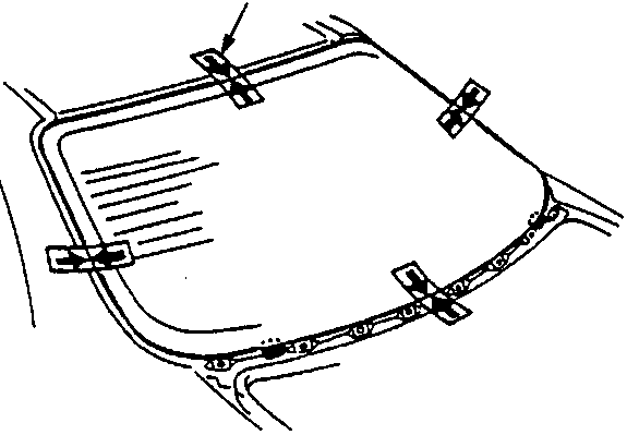
- Set rear screen upright on lower spacers, then centre the rear screen in the aperture. Make alignment marks across the rear screen and body with a wax crayon at the four points shown. Remove the rear screen carefully and set down face up.
- Apply cleaning solvent from the repair kit around the sealing surfaces of the body and rear screen.
CAUTION: Do not touch the cleaned surfaces, the primer may not bond to finger marks.
- Shake the primer tins from the repair kit for about 30 seconds.
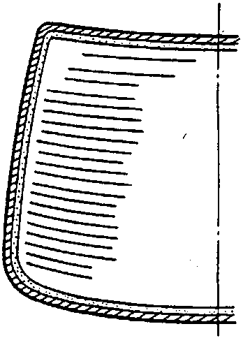
- Apply glass primer to the shaded area around the perimeter of the rear screen as shown, with the cotton bud applicator provided.
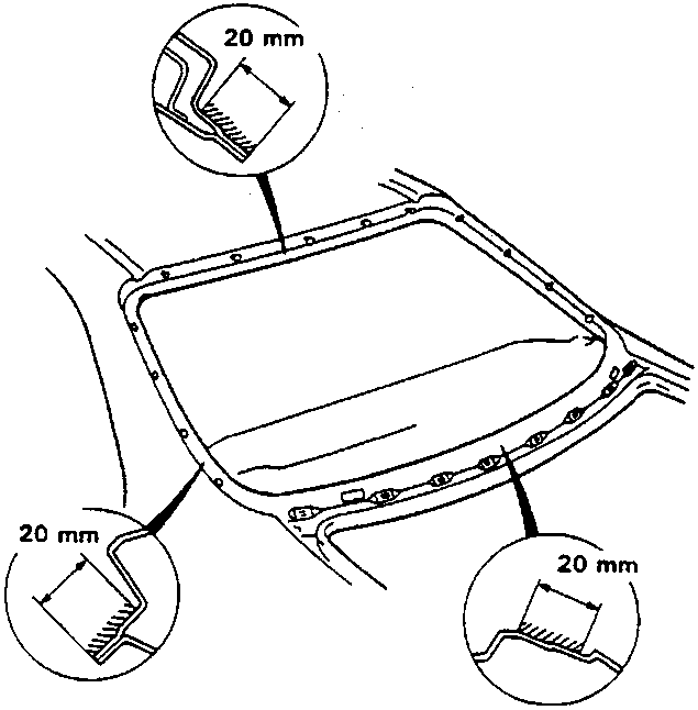
- Apply body primer to body flange with the cotton bud applicator provided ensuring spacing blocks are well primed.
Original page
Parts & tools for this job For Rover 600
- TOOLTrim removal tool kitSearch: trim removal tool kit
- PARTTouch-up paintSearch: Rover touch up paint
- PARTPanel clip assortmentSearch: Rover panel clips assortment
Links open Amazon search results in a new tab. As an Amazon Associate I earn from qualifying purchases.