
Replacement/Adjustment
- Make
- Rover
- Model
- 600 Rover 600 Repair Manual - Volumes 1 and 2 - 2nd Edition
- Section
- Exterior fittings › Replacement/Adjustment
BodyReplacement/Adjustment
Replacement/Adjustment
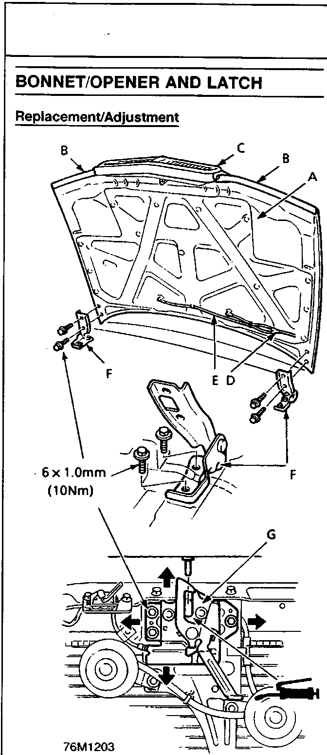
- A Bonnet
- B Headlight seals
- C Grille
- D Y - joint
- E Washer hose
- F Bonnet hinge
- G Bonnet latch
- Open the bonnet.
- Remove (8) plastic clips securing headlight seals.
- Remove radiator grille, see RADIATOR GRILLE.
- Apply protective covering to bonnet edges, front wings and bodywork.
- Slacken the bolts securing the bonnet to the hinges.
- Support the bonnet using an assistant and remove the bolts.
- Lift the bonnet clear of the vehicle.
Note:
- Take care not to scratch or damage the bonnet or grille.
- Use an assistant when removing and refitting the bonnet.
Parts & tools for this job For Rover 600
- TOOLTrim removal tool kitSearch: trim removal tool kit
- PARTTouch-up paintSearch: Rover touch up paint
- PARTPanel clip assortmentSearch: Rover panel clips assortment
Links open Amazon search results in a new tab. As an Amazon Associate I earn from qualifying purchases.