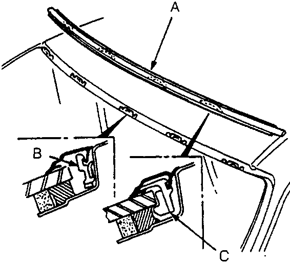
76M1061
A Upper moulding
B Upper clip (body)
C Upper clip (moulding)
15. Install the upper moulding.
17. Let the adhesive dry for at least 1 hour then test the windscreen seal for leaks, use either leak test equipment or spray with water.
CAUTION: If a leak is detected, dry the glass apply sealer to the area ensuring spacing blocks are well covered and retest. Do not attempt to remove windscreen or spread the adhesive already applied.
18. Refit air scoop and wipers, check that the ends of the side mouldings are set under the scoop. Reassemble all removed parts except the interior mirror.
CAUTION: Do not slam vehicle doors with the windows closed or drive the car at speed until the adhesive has completely cured. A curing time of 4 to 6 hours is desirable before driving the vehicle.
19. Refit interior mirror and clean glass.
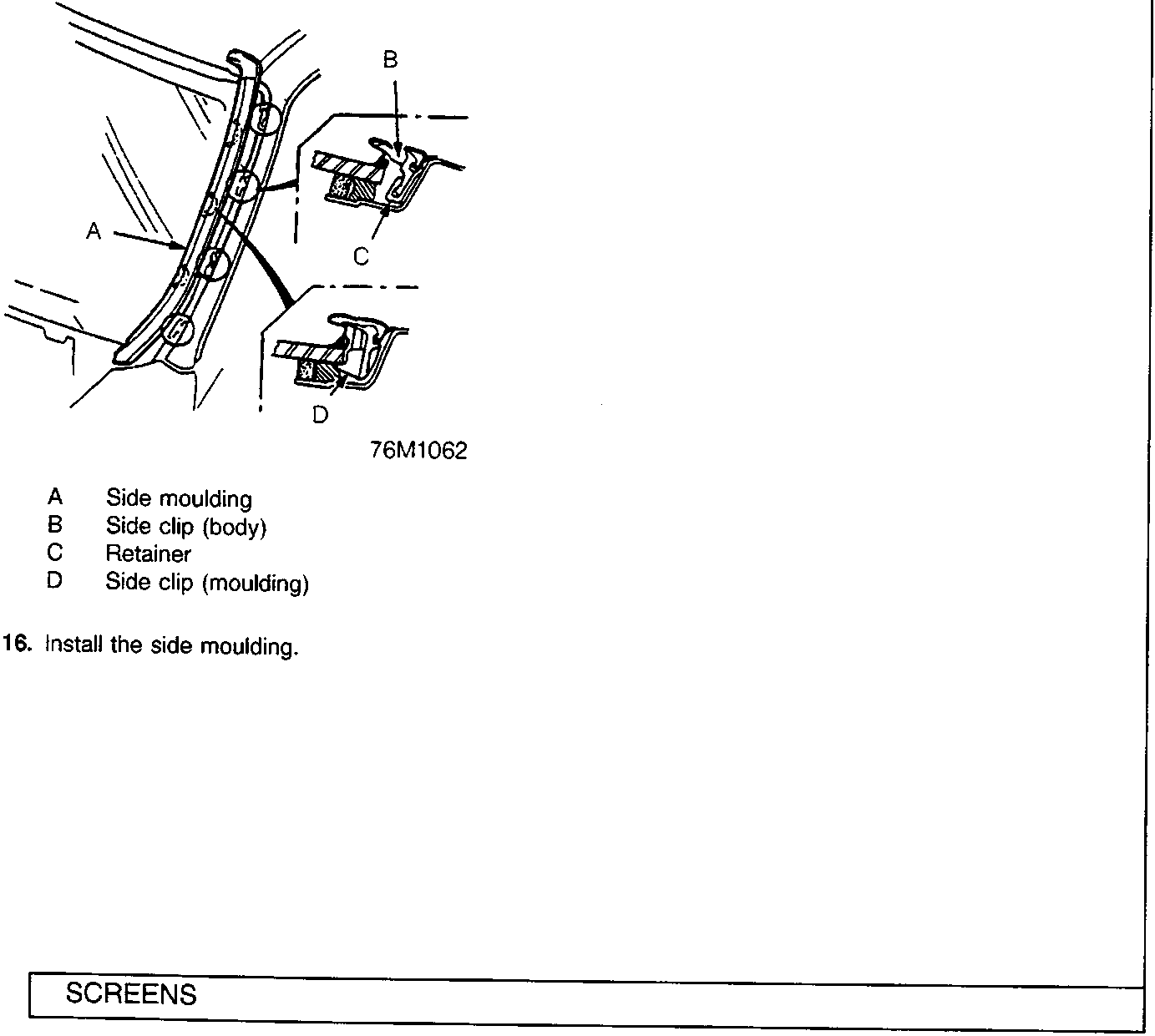
76M1062
A Side moulding
B Side clip (body)
C Retainer
D Side clip (moulding)
16. Install the side moulding.
Links open Amazon search results in a new tab. As an Amazon Associate I earn from qualifying purchases.
Help keep workshop manuals free
workshop-manuals.com provides free online workshop manuals.
If they helped you fix your car, please consider sharing or
making a small donation to keep the servers running.