
Installation (page 3 of 4)
- Make
- Rover
- Model
- 600 Rover 600 Repair Manual - Volumes 1 and 2 - 2nd Edition
- Section
- Exterior fittings
BodyInstallation · page 3 of 4
Note: Check the proper application of side clips (A, B, C).
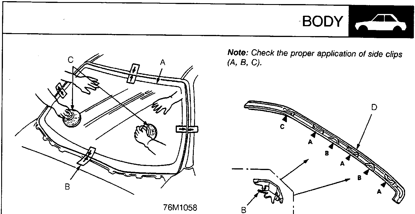
- Windscreen
- Alignment marks
- Suction cups
- Use the suction cups to hold the windscreen over the aperture, align it with the alignment marks made in step 3 then carefully lower into position against the L shaped spacers and set it down on the adhesive. Lightly push on the windscreen until its edge is fully seated on the adhesive all the way around.
Note: Do not close or open the doors until the adhesive is dry.
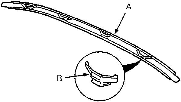
- Upper moulding
- Upper clip (4)
- Install the clips on the upper moulding and side moulding.
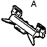
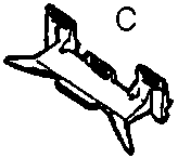
- Side clip (3)
- Side clip (2)
- Side clip (1)
Note: The numbers after the part description refer to the quantities of the parts used.
- Clean off the excess adhesive, remove protective tape.
Parts & tools for this job For Rover 600
- TOOLTrim removal tool kitSearch: trim removal tool kit
- PARTTouch-up paintSearch: Rover touch up paint
- PARTPanel clip assortmentSearch: Rover panel clips assortment
Links open Amazon search results in a new tab. As an Amazon Associate I earn from qualifying purchases.