Workshop Manuals Factory service & repair Rover
01 Information02 General data03 Engine04 Engine management system – PGM-Fi05 Cooling system, manifold and exhaust06 Clutch07 Manual gearbox08 Automatic gearbox09 Drive shafts10 Differential – manual gearbox11 Differential – automatic gearbox12 Steering13 Suspension14 Brakes and ABS15 Brakes – ABS BY416 Body17 Heating and ventilation18 Electrical19 Supplementary restraint system (SRS)
Rover Rover 600 Repair Manual - Volumes 1 and 2 - 2nd Edition16 · Body
16 · Body & interior

76M 0899 (page 3 of 3)

Make
Rover
Model
600 Rover 600 Repair Manual - Volumes 1 and 2 - 2nd Edition
Section
Interior fittings
Body76M 0899 · page 3 of 3
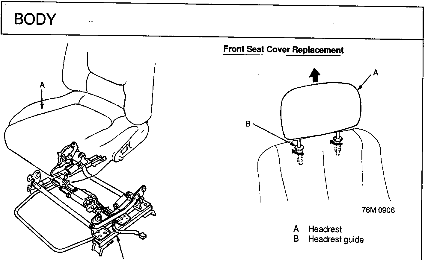
Diagram showing front seat assembly and headrest with callouts A and B
A Front seat B Seat device 7. Separate the front seat and seat device.
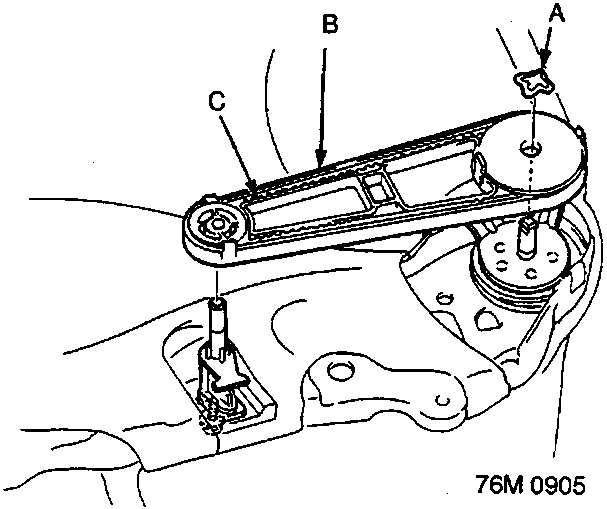
Diagram of recline belt tensioner mechanism with callouts A, B, and C
A Push nut B Recline belt tensioner C Recline belt
  • Replace push nut (item A).
8. If necessary, remove the recline belt tensioner. CAUTION: Wear gloves to remove and install the seat cover. Note: Take care not to tear the seams or damage the cover. Seat-back cover removal 1. Separate the front seat and seat device.
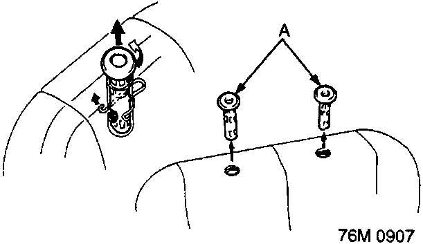
Diagram showing headrest guides being removed from seat back with callout A
A Headrest guide 2. Remove the headrest by turning the headrest guides. 3. Remove the headrest guides by turning them.

Installation is the reverse of the removal procedure.

Note:
  • Apply grease to the moving surfaces.
  • Do not apply grease to the recline belt.

Parts & tools for this job For Rover 600

Links open Amazon search results in a new tab. As an Amazon Associate I earn from qualifying purchases.