
Component Removal/Installation (page 3 of 3)
- Make
- Rover
- Model
- 600 Rover 600 Repair Manual - Volumes 1 and 2 - 2nd Edition
- Section
- Interior fittings
BodyComponent Removal/Installation · page 3 of 3
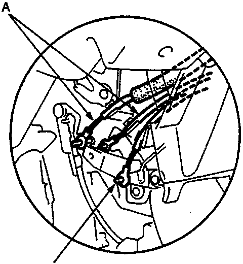
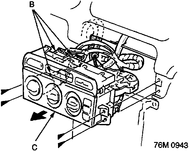
A Heater control cables
B Connectors
C Heater control panel
D Cool vent cable
- Screw locations and quantities are shown by black triangles.
- Remove the radio panel.
- Remove the screws and disconnect the heater control cables and connectors.
Parts & tools for this job For Rover 600
- TOOLTrim removal tool kitSearch: trim removal tool kit
- PARTTouch-up paintSearch: Rover touch up paint
- PARTPanel clip assortmentSearch: Rover panel clips assortment
Links open Amazon search results in a new tab. As an Amazon Associate I earn from qualifying purchases.