
Original page (page 12 of 13)
- Make
- Rover
- Model
- 600 Rover 600 Repair Manual - Volumes 1 and 2 - 2nd Edition
- Section
- Repairs
Manual gearboxOriginal page · page 12 of 13
- Install the vehicle speed sensor sensor, then connect.
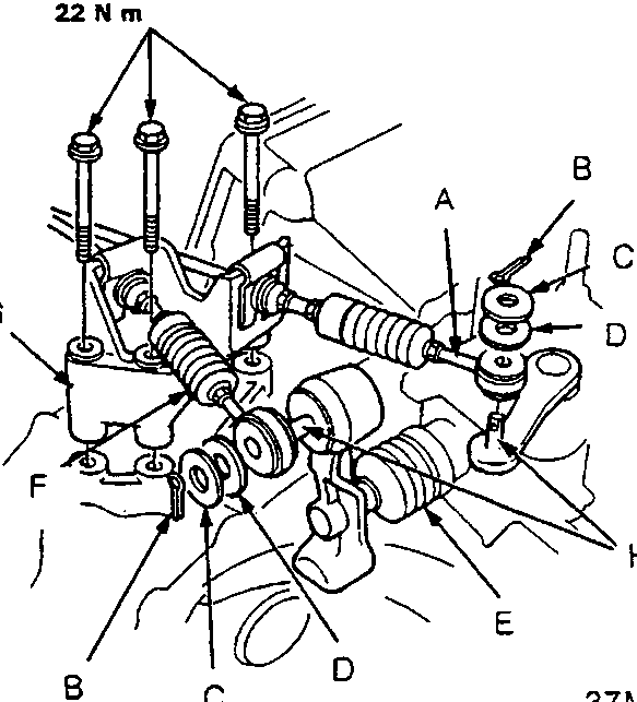
- Select cable
- Cotter pin
- Steel washer
- Plastic washer. Inspect for wear and damage.
- Boot
- Shift cable
- Cable bracket
- Grease
- Install the shift cable and select cable to the shift lever and to select lever respectively. Replace the cotter pin.
CAUTION: Take care not to bend the cables.
Note: Turn the boot of the shift lever so the hole is facing down.
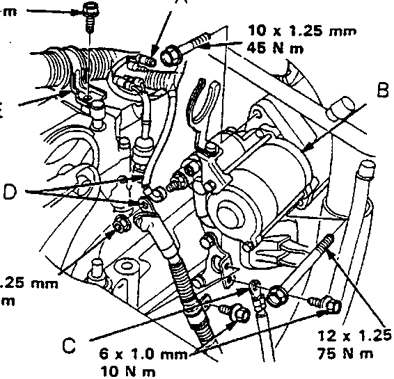
- Reverse light switch connectors
- Starter motor
- Earth cable
- Starter motor cables
- Wire harness clamp
- Connect the gearbox earth cable and reverse light switch connectors.
- Install the wire harness clamp.
- Install the starter motor, then connect the starter motor cables, see ELECTRICAL.
Note: When installing the starter motor cable, make sure that the crimped side of the ring terminal is facing out.
Parts & tools for this job For Rover 600
- PARTClutch kitSearch: Rover 600 clutch kit
- TOOLClutch alignment toolSearch: clutch alignment tool
- FLUIDGear oilSearch: Rover 600 manual gearbox oil
Links open Amazon search results in a new tab. As an Amazon Associate I earn from qualifying purchases.