
Original page (page 8 of 13)
- Make
- Rover
- Model
- 600 Rover 600 Repair Manual - Volumes 1 and 2 - 2nd Edition
- Section
- Repairs
Manual gearboxOriginal page · page 8 of 13
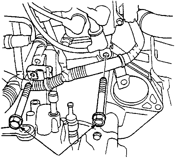
A Gearbox housing mounting bolts
- Install the two upper gearbox housing mounting bolts.
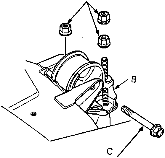
| A | Step 2 – tighten |
| B | Gearbox mount |
| C | Step 1 – tighten temporarily Step 3 – tighten |
- Raise the gearbox, then install the gearbox mount.
- Torque mounting bolts and nuts in sequence shown.
- Make sure the bushings are not twisted or offset.
Parts & tools for this job For Rover 600
- PARTClutch kitSearch: Rover 600 clutch kit
- TOOLClutch alignment toolSearch: clutch alignment tool
- FLUIDGear oilSearch: Rover 600 manual gearbox oil
Links open Amazon search results in a new tab. As an Amazon Associate I earn from qualifying purchases.