Workshop Manuals Factory service & repair Rover
01 Information02 General data03 Engine04 Engine management system – PGM-Fi05 Cooling system, manifold and exhaust06 Clutch07 Manual gearbox08 Automatic gearbox09 Drive shafts10 Differential – manual gearbox11 Differential – automatic gearbox12 Steering13 Suspension14 Brakes and ABS15 Brakes – ABS BY416 Body17 Heating and ventilation18 Electrical19 Supplementary restraint system (SRS)
Rover Rover 600 Repair Manual - Volumes 1 and 2 - 2nd Edition07 · Manual gearbox
07 · Transmission

Original page (page 6 of 13)

Make
Rover
Model
600 Rover 600 Repair Manual - Volumes 1 and 2 - 2nd Edition
Section
Repairs
Manual gearboxOriginal page · page 6 of 13
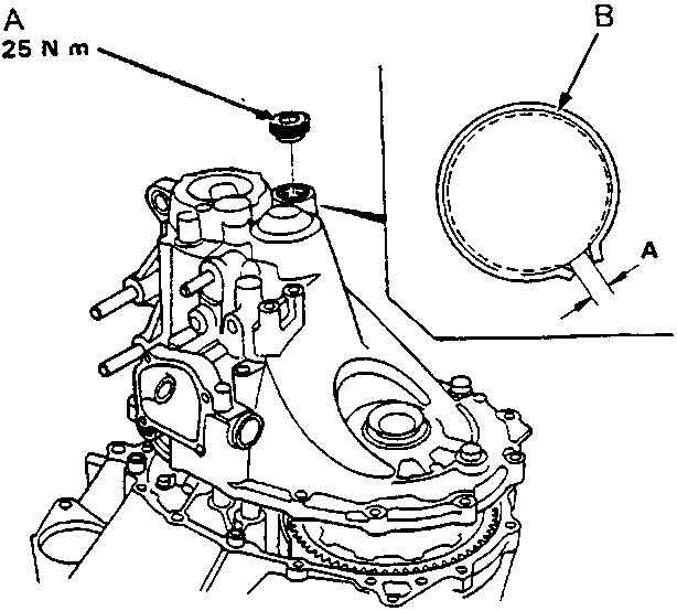
Diagram of gearbox with sealing bolt and snap ring labeled A and B, torque value 25 N m
A Sealing bolt B Snap ring Dimension A as installed: 3.60 ÷ 6.32 mm 13. Install the 32 mm sealing bolt.

Note: Apply liquid gasket to the threads.
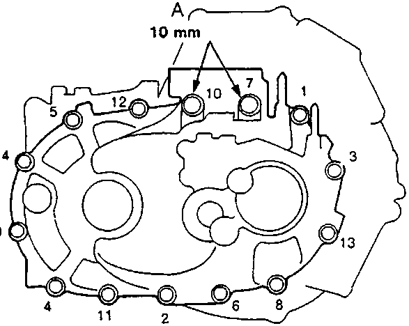
Diagram of gearbox cover showing bolt tightening sequence 1-14 and dimension A of 10 mm
A Bolts 14. Torque the bolts in a crisscross pattern in several steps as shown.
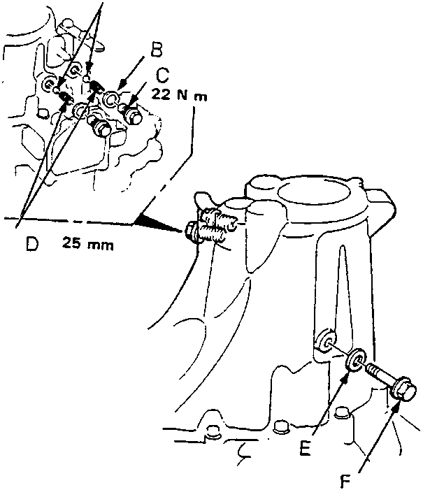
Diagram of reverse idler gear shaft assembly with components A-F labeled, showing dimension D of 25 mm and torque values 22 N m and 55 N m
A Steel ball B Washer C Setting screw D Spring E Washer F Reverse idler gear shaft bolt 15. Install the reverse idler gear shaft bolt. 16. Install the steel balls, springs, washers and setting screws. 17. Install the shift arm assembly. 18. Shift the gearbox through all the gears before installing it.

Parts & tools for this job For Rover 600

Links open Amazon search results in a new tab. As an Amazon Associate I earn from qualifying purchases.