
Original page (page 13 of 13)
- Make
- Rover
- Model
- 600 Rover 600 Repair Manual - Volumes 1 and 2 - 2nd Edition
- Section
- Repairs
Manual gearboxOriginal page · page 13 of 13
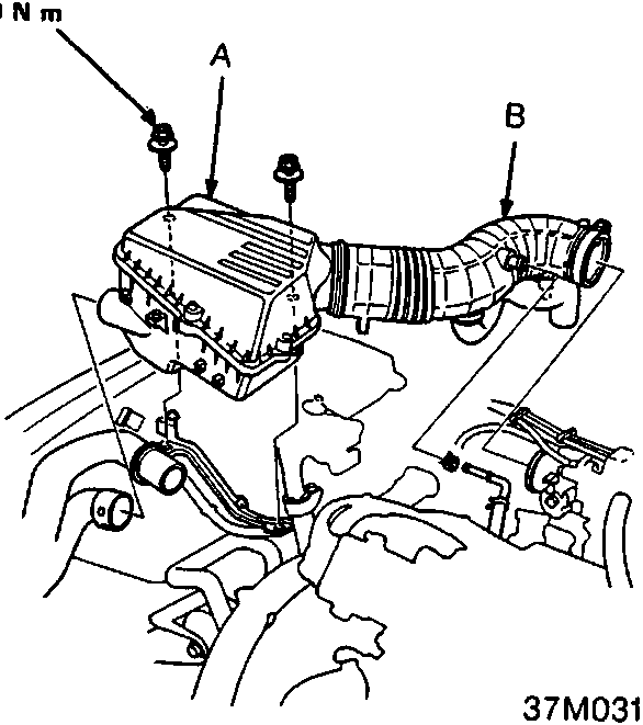
- A A Air cleaner assembly
- B B Intake air duct
- Install the air cleaner assembly and intake air duct, see ENGINE MANAGEMENT SYSTEM – PGM-Fi.
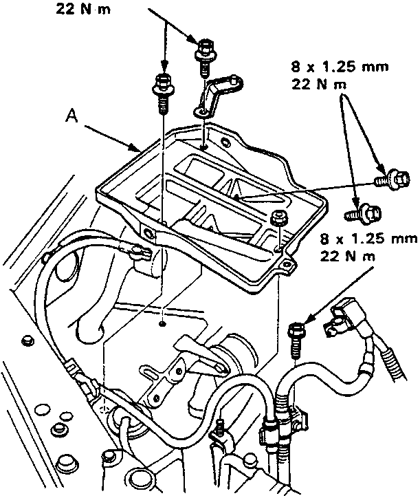
- A A Battery base
- Install the battery base.
- Refill the gearbox with oil .
- Install the battery, then connect the battery positive ( + ) and negative ( − ) cables to the battery.
- Check the clutch operation.
- Shift the gear lever and check for smooth operation.
- Check the front wheel alignment, see SUSPENSION .
Parts & tools for this job For Rover 600
- PARTClutch kitSearch: Rover 600 clutch kit
- TOOLClutch alignment toolSearch: clutch alignment tool
- FLUIDGear oilSearch: Rover 600 manual gearbox oil
Links open Amazon search results in a new tab. As an Amazon Associate I earn from qualifying purchases.