
Air conditioning models only
- Make
- Rover
- Model
- Coupé, Cabriolet & Tourer 200/400 Coupé, Cabriolet & Tourer Workshop Manual
- Section
- Repairs › Air conditioning models only
Manifold and exhaustAir conditioning models only
- Remove bolt securing dipstick tube to coolant rail.
- Slacken clip and disconnect coolant rail hose from thermostat housing.
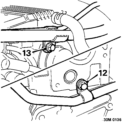
- Remove bolt securing coolant rail to cylinder head.
- Air conditioning models only: Remove bolt securing air conditioning pipe bracket to cylinder head.
Air conditioning models only
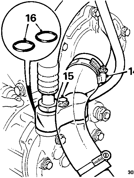
- Slacken clip and release coolant rail hose from water pump.
- Remove bolt securing air conditioning pipe manifold to compressor.
- Remove and discard 'O' ring seals from compressor.
CAUTION: Plug the connections.
- Carefully position air conditioning pipes and coolant hoses aside to enable exhaust manifold to be withdrawn.
All models
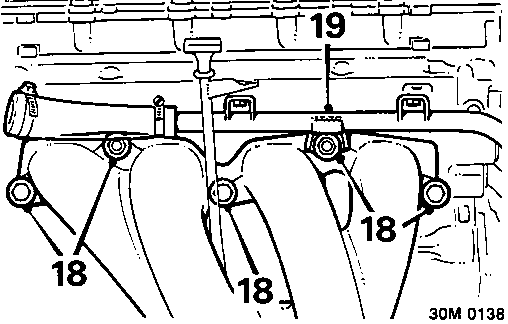
- Remove 3 bolts and 2 nuts securing exhaust manifold to cylinder head.
- Release coolant rail bracket from manifold stud.
- Release manifold from cylinder head and carefully manoeuvre from vehicle.
- Remove and discard manifold gasket
Refit
- Clean mating faces of exhaust manifold and cylinder head.
- Fit new gasket to cylinder head.
- Manoeuvre manifold into position and align to cylinder head.
- Fit coolant rail bracket to manifold stud.
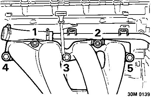
- Working in the sequence shown, fit and tighten exhaust manifold nuts and bolts to 45 Nm.
Air conditioning models only
- Fit new 'O' ring seals to compressor.
- Align air conditioning pipe manifold to compressor, fit bolt and tighten to 45 Nm.
- Connect coolant rail hose to water pump and tighten clip.
- Align air conditioning pipe bracket to cylinder head, fit bolt and tighten to 10 Nm.
All models
- Align coolant rail to cylinder head, fit bolt and tighten to 25 Nm.
- Connect coolant rail hose to thermostat housing and tighten clip.
- Align dipstick tube to coolant rail, fit and tighten bolt to 9 Nm.
Parts & tools for this job For Rover Coupé, Cabriolet & Tourer
- TOOLA/C manifold gauge setSearch: AC manifold gauge set
- TOOLUV leak detection kitSearch: AC UV leak detection kit
- PARTCabin filterSearch: Rover Coupé, Cabriolet & Tourer cabin filter
Links open Amazon search results in a new tab. As an Amazon Associate I earn from qualifying purchases.