
Refit
- Make
- Rover
- Model
- Coupé, Cabriolet & Tourer 200/400 Coupé, Cabriolet & Tourer Workshop Manual
- Section
- Repairs › Refit
Manifold and exhaustRefit
- Disconnect breather hose from inlet manifold.
- Depress plastic collar to release quick fit connector and disconnect brake servo hose from inlet manifold.
- Disconnect ECU vacuum pipe from inlet manifold.
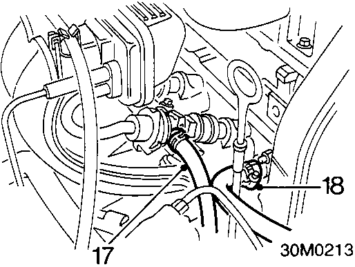
- Release clip, disconnect fuel return hose from fuel rail.
CAUTION: Plug the connections.
- Slacken clip, disconnect expansion tank hose from inlet manifold.
- Release fuel return hose from clips.
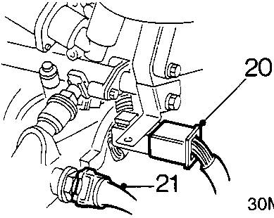
- Release injector harness multiplug from bracket, disconnect multiplug.
- Disconnect multiplug from air temperature sensor.
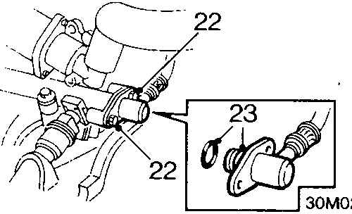
- Remove 2 bolts securing fuel feed pipe to fuel rail.
- Release fuel feed pipe from fuel rail, remove and discard 'O' ring.
CAUTION: Plug the connections.
- Working from the centre outwards, progressively slacken then remove 3 nuts and 4 bolts securing inlet manifold to cylinder head.
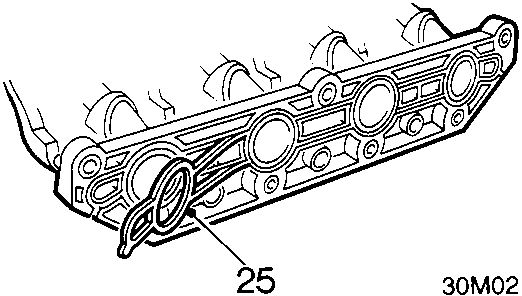
- Remove inlet manifold, remove and discard gasket.
Refit
- Ensure mating surfaces are clean and that metal inserts are fitted in inlet manifold stud and bolt holes.
- Fit new gasket, position inlet manifold to studs.
CAUTION: Gasket must be fitted dry.
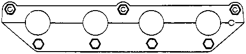
- Fit bolts and nuts and tighten in sequence shown to 25 Nm.
- Connect expansion tank hose to inlet manifold, tighten clip.
- Lubricate a new 'O' ring with silicone grease and position to fuel feed pipe.
- Position fuel feed pipe to fuel rail, fit bolts and tighten to 10 Nm.
- Connect multiplug to air temperature sensor.
- Connect multiplug to injector harness, secure multiplug to bracket.
- Connect fuel return hose to fuel rail, tighten clip.
- Secure fuel return hose in clips.
- Connect ECU vacuum pipe and brake servo vacuum hoses to inlet manifold.
- Connect breather pipe to inlet manifold.
- Connect multiplug to stepper motor.
- Clean inlet manifold and throttle housing mating surfaces.
- Lubricate a new 'O' ring with silicone grease and fit to throttle housing.
- Position throttle housing to inlet manifold, fit bolts and tighten to 4 Nm.
- Secure throttle cable in clip.
- Connect multiplug to throttle potentiometer.
- Connect breather hose to throttle housing, tighten clip.
- Connect hose to stepper motor, secure clip.
- Connect purge hose to inlet manifold, tighten clip.
Parts & tools for this job For Rover Coupé, Cabriolet & Tourer
- PARTExhaust gasketSearch: Rover Coupé, Cabriolet & Tourer exhaust gasket
- TOOLPenetrating oilSearch: penetrating oil
- TOOLOBD2 scannerSearch: OBD2 scanner
Links open Amazon search results in a new tab. As an Amazon Associate I earn from qualifying purchases.