
Exhaust manifold gasket – 2.0 – turbo
- Make
- Rover
- Model
- Coupé, Cabriolet & Tourer 200/400 Coupé, Cabriolet & Tourer Workshop Manual
- Section
- Repairs › Exhaust manifold gasket – 2.0 – turbo
Manifold and exhaustExhaust manifold gasket – 2.0 – turbo
- Air conditioning models only: Align air conditioning pipe bracket to coolant rail, fit and tighten bolt to 9 Nm.
- Connect oxygen sensor multiplug.
- Fit new exhaust front pipe gasket.
- Align exhaust front pipe to manifold, fit nuts and tighten diagonally to 45 Nm.
- Air conditioning models only: Fit alternator, see ELECTRICAL – Repairs.
- Refill cooling system, see MAINTENANCE.
- Refit air cleaner, see MODULAR ENGINE MANAGEMENT SYSTEM – MPi – Repairs
- Refit battery, position battery clamp and tighten bolt to 9 Nm.
- Connect both battery leads.
EXHAUST MANIFOLD GASKET – 2.0 – TURBO
Service Repair No. 30.15.12
Remove
- Remove intercooler, see MODULAR ENGINE MANAGEMENT SYSTEM – MPi – Repairs.
- Drain cooling system, see MAINTENANCE.
- Air conditioning models only: Remove alternator, see ELECTRICAL – Repairs.
- Remove exhaust front pipe.
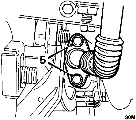
- Remove 2 bolts securing oil drain pipe to turbocharger, remove and discard gasket.
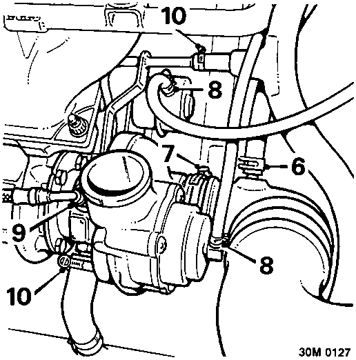
- Release clip and disconnect breather hose from turbocharger intake hose.
- Slacken clip and disconnect intake hose from turbocharger.
- Release clips and disconnect 2 vacuum hoses from turbocharger.
- Slacken oil feed pipe union and disconnect oil feed pipe from turbocharger.
CAUTION: Plug the connections.
- Slacken clips and disconnect 2 coolant hoses from turbocharger.
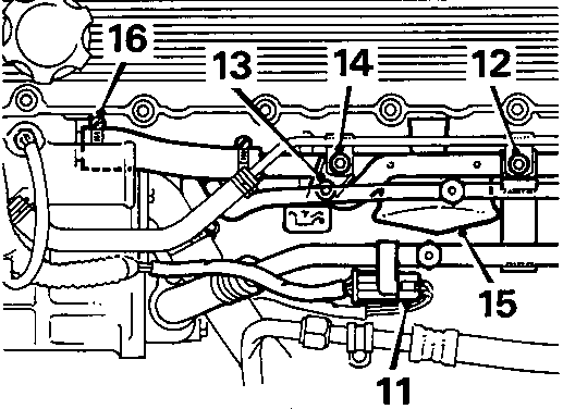
- Disconnect oxygen sensor multiplug.
- Air conditioning models only: Remove bolt securing air conditioning pipe bracket to coolant rail.
- Remove bolt securing dipstick tube to coolant rail.
- Remove bolt securing dipstick tube to turbocharger hose heat shield.
- Remove turbocharger hose heat shield.
- Slacken clip and disconnect coolant rail hose from thermostat housing.
Parts & tools for this job For Rover Coupé, Cabriolet & Tourer
- PARTExhaust gasketSearch: Rover Coupé, Cabriolet & Tourer exhaust gasket
- TOOLPenetrating oilSearch: penetrating oil
- TOOLOBD2 scannerSearch: OBD2 scanner
Links open Amazon search results in a new tab. As an Amazon Associate I earn from qualifying purchases.