
Remove
- Make
- Rover
- Model
- Coupé, Cabriolet & Tourer 200/400 Coupé, Cabriolet & Tourer Workshop Manual
- Section
- Repairs › Remove
Manifold and exhaustRemove
Service Repair No. 30.15.37
Remove
- Disconnect battery earth lead.
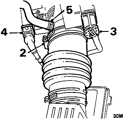
- Slacken clip and disconnect hose from throttle housing.
- Disconnect multiplug from stepper motor.
- Disconnect multiplug from throttle potentiometer.
- Disconnect breather hose from throttle housing.
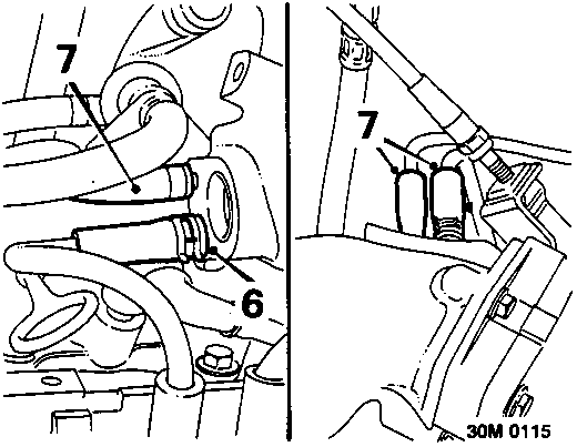
- Release clip, disconnect breather pipe from manifold chamber.
- Release clips and disconnect 3 breather hoses from manifold chamber.
- Remove banjo bolt securing brake servo hose union to manifold chamber, discard 2 sealing washers.
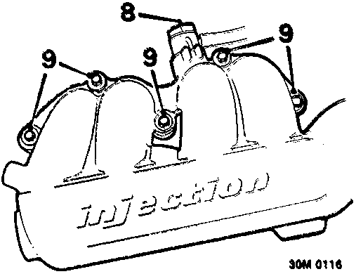
- Remove 5 bolts securing manifold chamber to inlet manifold.
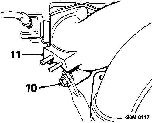
- Remove bolt securing support stay to manifold chamber.
- Lift manifold chamber off inlet manifold and move aside.
- Remove and discard gasket.
Refit
- Ensure mating faces of manifold chamber and inlet manifold are clean.
- Position a new gasket to inlet manifold.
- Fit manifold chamber.
- Fit manifold chamber securing bolts and tighten progressively to 10 Nm.
- Position support stay to manifold chamber fit and tighten bolt to 25 Nm.
- Position 2 new sealing washers either side of brake servo hose union, position union to manifold chamber ensuring pin on union locates in groove.
- Fit banjo bolt and tighten to 50 Nm.
- Connect breather hoses to manifold, secure clips.
- Connect breather pipe to manifold chamber, secure clip.
- Connect breather hose to throttle housing.
- Connect multiplugs to stepper motor and throttle potentiometer.
- Connect hose to throttle housing and tighten clip.
- Connect battery earth lead.
Parts & tools for this job For Rover Coupé, Cabriolet & Tourer
- PARTExhaust gasketSearch: Rover Coupé, Cabriolet & Tourer exhaust gasket
- TOOLPenetrating oilSearch: penetrating oil
- TOOLOBD2 scannerSearch: OBD2 scanner
Links open Amazon search results in a new tab. As an Amazon Associate I earn from qualifying purchases.