
Front pipe and flange gasket – k8
- Make
- Rover
- Model
- Coupé, Cabriolet & Tourer 200/400 Coupé, Cabriolet & Tourer Workshop Manual
- Section
- Repairs › Front pipe and flange gasket – k8
Manifold and exhaustFront pipe and flange gasket – k8 · page 1 of 2
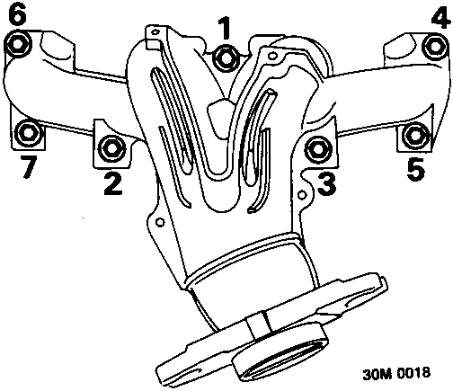
- Fit nuts securing manifold and, working in the sequence illustrated, tighten to 45 Nm.
- Position intake duct to air cleaner and secure with clips.
- Align duct to brackets, fit and tighten bolts.
- Connect vacuum hose to air temperature control valve.
- Position intake hose adaptor to body, fit and tighten screws.
- Position exhaust pipe, complete with gasket, to manifold flange and fit flat washers and nuts.
- Tighten exhaust pipe to manifold nuts to 50 Nm.
- Remove stand(s) and lower vehicle.
- Connect battery earth lead.
FRONT PIPE AND FLANGE GASKET – K8
Service Repair No. 30.10.09
Remove
- Disconnect battery earth lead.
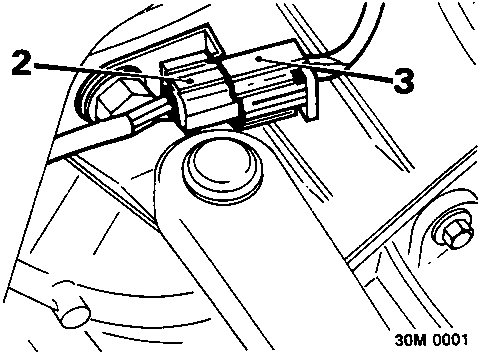
- Release oxygen sensor multiplug from bracket on gearbox.
- Disconnect oxygen sensor multiplug from engine harness.
- Raise vehicle on a ramp.
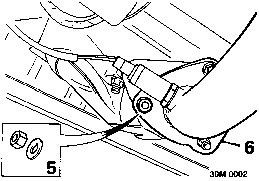
- Remove 3 nuts securing exhaust pipe to manifold flange and collect washers.
- Disconnect exhaust front pipe from manifold; discard gasket.
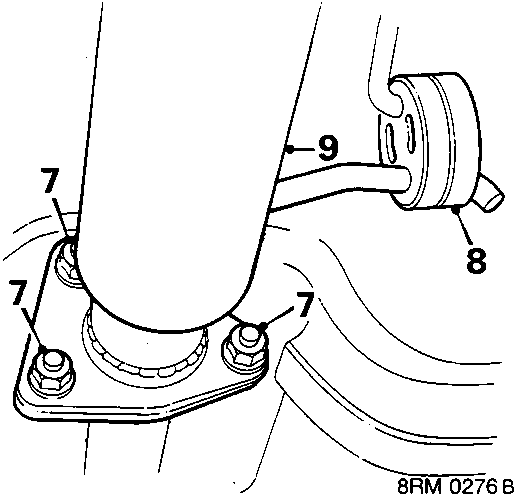
- Remove 3 nuts securing front pipe to catalytic converter.
- Release front mounting rubber.
- Separate front pipe from catalytic converter.
- Remove and discard gasket.
- Remove front pipe.
Do not carry out further dismantling if component is removed for access only
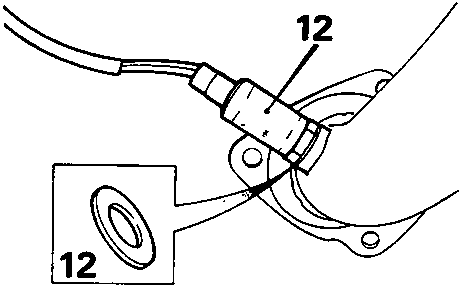
- Remove oxygen sensor and seal.
Refit
- Fit oxygen sensor, use a new seal.
- Clean mating faces of front pipe.
Parts & tools for this job For Rover Coupé, Cabriolet & Tourer
- PARTExhaust gasketSearch: Rover Coupé, Cabriolet & Tourer exhaust gasket
- TOOLPenetrating oilSearch: penetrating oil
- TOOLOBD2 scannerSearch: OBD2 scanner
Links open Amazon search results in a new tab. As an Amazon Associate I earn from qualifying purchases.