
Manifold heater – k8
- Make
- Rover
- Model
- Coupé, Cabriolet & Tourer 200/400 Coupé, Cabriolet & Tourer Workshop Manual
- Section
- Repairs › Manifold heater – k8
Manifold and exhaustManifold heater – k8
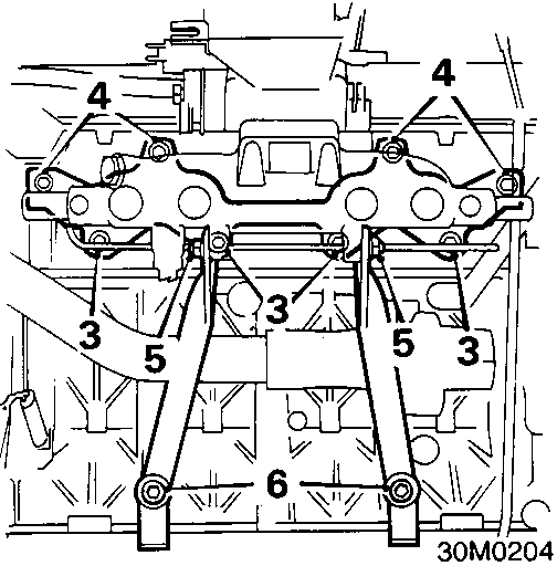
MANIFOLD HEATER – K8
Service Repair No. 30.15.34
Remove
- Remove inlet manifold and discard gasket.,
- Remove 4 lower bolts securing inlet manifold to cylinder head.
- Remove 2 upper bolts and 2 nuts securing inlet manifold to cylinder head.
- Remove 2 bolts securing support strut to inlet manifold.
- Slacken 2 bolts securing support struts to cylinder block.
- Release inlet manifold from studs, remove and discard gasket.
Refit
- Clean all traces of gasket material from mating faces.
- Position new gasket to cylinder head studs.
- Position inlet manifold on studs.
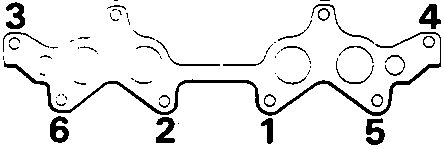
- Fit bolts and nuts and tighten in sequence shown to 25 Nm.
- Position support struts to inlet manifold, fit and tighten bolts to 25 Nm.
- Tighten support strut to cylinder block bolts to 25 Nm.
- Refill cooling system, see MAINTENANCE.
- Fit air cleaner, see MODULAR ENGINE MANAGEMENT SYSTEM – SPi – Repairs.
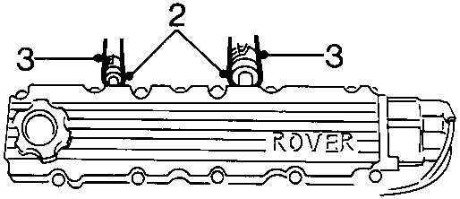
- Release 2 clips securing breather hoses to camshaft cover.
- Disconnect breather hoses.
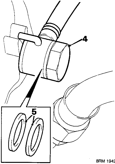
- Remove brake servo banjo bolt from manifold.
- Remove and discard sealing washers.
Parts & tools for this job For Rover Coupé, Cabriolet & Tourer
- TOOLA/C manifold gauge setSearch: AC manifold gauge set
- TOOLUV leak detection kitSearch: AC UV leak detection kit
- PARTCabin filterSearch: Rover Coupé, Cabriolet & Tourer cabin filter
Links open Amazon search results in a new tab. As an Amazon Associate I earn from qualifying purchases.