
Original page (page 2 of 2)
- Make
- Rover
- Model
- 600 Rover 600 Repair Manual - Volumes 1 and 2 - 2nd Edition
- Section
- Doors
BodyOriginal page · page 2 of 2
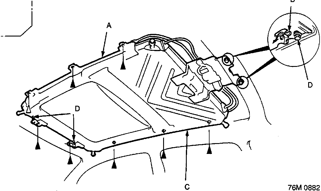
- Loosen the rear bolts.
A Frame seal
B Rear hook
C Frame
- Bolt locations and quantities are shown by black triangles.
- Loosen the rear bolt at position D'.
- Remove the eight bolts and detach the rear hooks, then remove the frame from the car.
Note: You may require assistance when removing the frame.
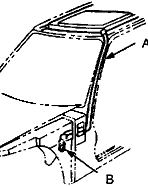
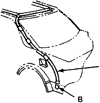
A Front drain tube
B Drain valve
C Rear drain tube
- Pull the drain tubes out the front and rear pillars.
Note: Before pulling out the drain tube, tie a string to the end of it so it can be reinstalled.
- Installation is the reverse of the removal procedure.
Note:
- Clean the surface of the frame.
- Check the frame seal.
- Check for water leaks.
Parts & tools for this job For Rover 600
- TOOLTrim removal tool kitSearch: trim removal tool kit
- PARTTouch-up paintSearch: Rover touch up paint
- PARTPanel clip assortmentSearch: Rover panel clips assortment
Links open Amazon search results in a new tab. As an Amazon Associate I earn from qualifying purchases.