
Replacement (page 2 of 2)
- Make
- Rover
- Model
- 600 Rover 600 Repair Manual - Volumes 1 and 2 - 2nd Edition
- Section
- Doors
BodyReplacement · page 2 of 2
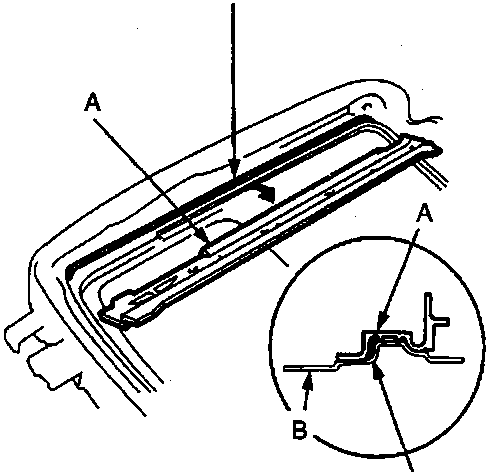
- A Guide rail
- B Frame
- Apply caulking at positions 'C' and 'D'.
- Remove the guide rails.
Note: To install, apply the caulking to guide rail mount faces of the frame.
- Installation is the reverse of the removal procedure.
Note:
- Damaged parts should be replaced.
- Apply grease to the sliding portion.
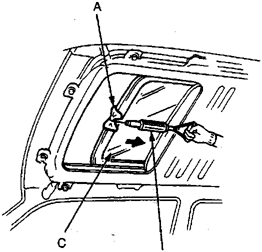
- A Cloth
- B Spring scale
- C Glass
Before installing the motor, measure the effort required to open the glass using a spring scale as shown.
CAUTION: When using a spring scale, protect the leading edge of the glass with a cloth.
If load is over 100 N (10 kg, 22 lbs), check side clearance and glass height adjustment.
Parts & tools for this job For Rover 600
- TOOLTrim removal tool kitSearch: trim removal tool kit
- PARTTouch-up paintSearch: Rover touch up paint
- PARTPanel clip assortmentSearch: Rover panel clips assortment
Links open Amazon search results in a new tab. As an Amazon Associate I earn from qualifying purchases.