
1.4 & 1.6 models
- Make
- Rover
- Model
- 200 Workshop Manual
- Year
- 1995–1999
- Section
- Repairs › 1.4 & 1.6 models
Engine - K161.4 & 1.6 models · page 1 of 2
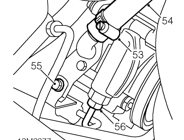
- Loosen clip securing fluid inlet hose to power steering pump.
- Disconnect fluid inlet hose from power steering pump.
- Remove bolt securing fluid outlet hose clamp to bracket.
- Loosen union and disconnect fluid outlet hose from power steering pump.
CAUTION: To prevent damage to pipes and components use two spanners when loosening or tightening unions.
- Remove and discard ’O’ ring from fluid outlet hose.
- Plug hose and power steering pump connections to prevent excess fluid loss and the ingress of dirt into the system.
1.4 & 1.6 models
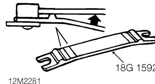
- Using tool 18G 1592 release gear selector linkage ball joint from gear selector lever.
- Using tool 18G 1592 release gear change linkage ball joint from gear change lever.
1.8 Models
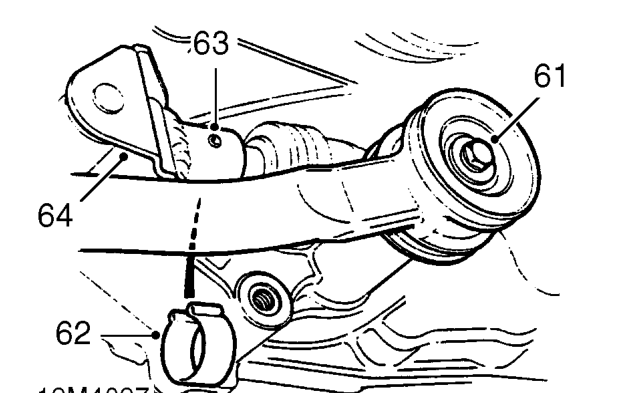
- Remove bolt and disconnect gear change steady bar from gearbox. Collect 2 washers.
- Remove clip retaining selector rod roll pin.
- Using a suitable punch, drive out roll pin securing selector rod to selector shaft.
- Release selector rod from selector shaft and tie aside.
All models
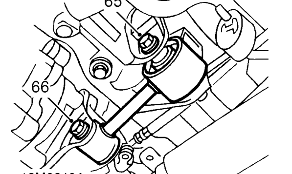
1.4 model illustrated
- Loosen through bolt securing engine steady bar to subframe.
- Remove through bolt securing engine steady bar to bracket on gearbox/sump.
Parts & tools for this job For 1995 Rover 200
- PARTEngine gasket setSearch: Rover 200 1995 engine gasket set
- TOOLTorque wrenchSearch: 3/8 inch torque wrench
- TOOLFeeler gauge setSearch: feeler gauge set
Links open Amazon search results in a new tab. As an Amazon Associate I earn from qualifying purchases.