
Mass Production Body Welding Diagram - face view
- Make
- Rover
- Model
- 400 Body Repair Manual
- Year
- 1995–2000
- Section
- Repairs › Mass Production Body Welding Diagram - face view
Panel repairsMass Production Body Welding Diagram - face view
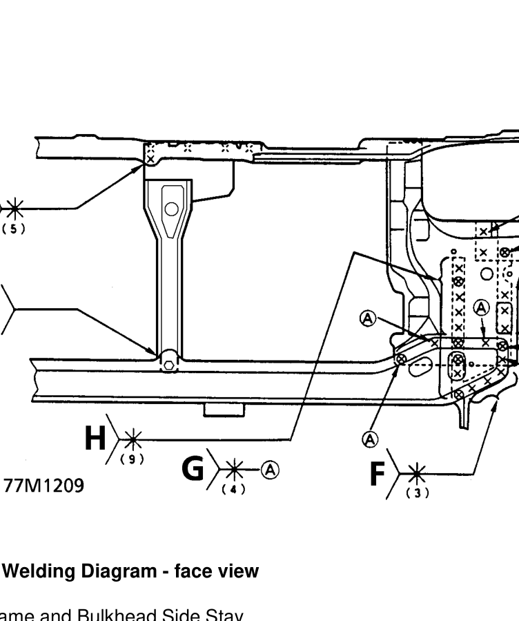
Mass Production Body Welding Diagram - face view
A. Bulkhead Upper Frame and Bulkhead Side Stay B. Bulkhead side stay and Front side bulkhead C. Front side bulkhead, Bulkhead side stay and Front back plate extension D. Front side bulkhead and Front back plate extension E. Front lower cross member, Front side bulkhead and Back plate extension F. Front lower cross member and Back plate extension G. Front lower cross member and Front side bulkhead H. Front side bulkhead, Front lower cross member and Tie down bracket (include 3 points of 3-plate welding) J. Centre stay and Front lower cross member K. Bulkhead upper frame and Centre stay/bonnet latch bracket.
Parts & tools for this job For 1995 Rover 400
- TOOLTrim removal tool kitSearch: trim removal tool kit
- PARTTouch-up paintSearch: Rover touch up paint
- PARTPanel clip assortmentSearch: Rover panel clips assortment
Links open Amazon search results in a new tab. As an Amazon Associate I earn from qualifying purchases.