
Replacement (page 2 of 3)
- Make
- Rover
- Model
- 600 Rover 600 Repair Manual - Volumes 1 and 2 - 2nd Edition
- Section
- Doors
BodyReplacement · page 2 of 3
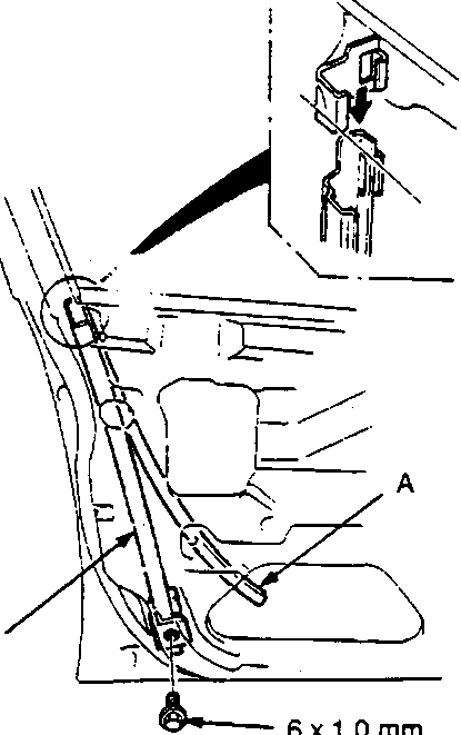
8 Nm
A Glass run channel
B Centre channel
- Remove the front and centre channels.
Note: To install, fit the glass run channel into the front and rear channels as shown.
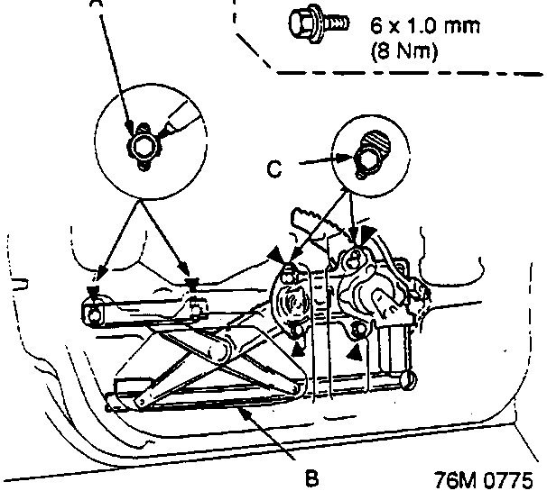
A Roller guide bolts
B Regulator
C Upper bolts – Regulator
Note:
- Scribe a line around the roller guide bolts to show their original positions.
- Bolt locations and quantities are shown by black triangles.
- Remove the two lower bolts and loosen the two upper bolts. Loosen the roller guide bolts and disconnect the connector. Take out the regulator through the centre hole in the door.
Parts & tools for this job For Rover 600
- TOOLTrim removal tool kitSearch: trim removal tool kit
- PARTTouch-up paintSearch: Rover touch up paint
- PARTPanel clip assortmentSearch: Rover panel clips assortment
Links open Amazon search results in a new tab. As an Amazon Associate I earn from qualifying purchases.