
Front headlining – coupe
- Make
- Rover
- Model
- Coupé, Cabriolet & Tourer 200/400 Coupé, Cabriolet & Tourer Workshop Manual
- Section
- Interior trim components › Front headlining – coupe
BodyFront headlining – coupe
FRONT HEADLINING – COUPE
Service Repair No. 76.64.01
Remove
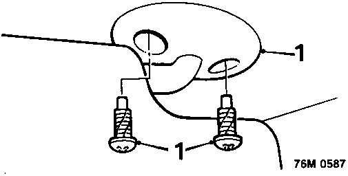
- Release sun visors from clips, remove 2 screws securing each visor and remove sun visors.
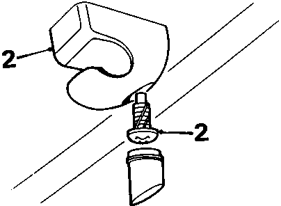
- Remove inserts and screws securing sun visor clips and remove clips.
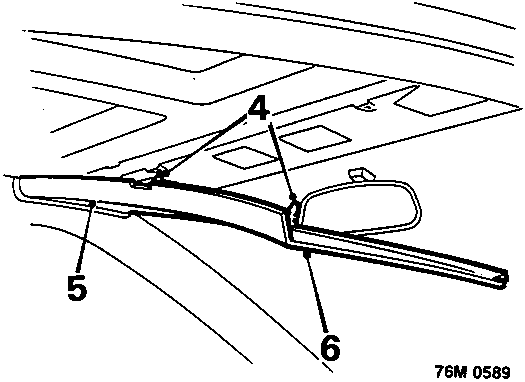
- Remove one 'A' post trim panel, see 'A post trim – Coupe.
- Disengage 2 trim studs securing front headlining to roof.
- Release headlining from beneath remaining 'A' post trim.
- Remove front headlining.
Refit
- Position front headlining and engage beneath 'A' post trim.
- Engage front headlining trim studs.
- Fit 'A' post trim panel, see 'A post trim – Coupe.
- Fit sun visors.
- Fit sun visor clips. Engage visors in clips.
REAR HEADLINING – COUPE
Service Repair No. 76.64.03
Remove
- Remove roof lamp assembly, see ELECTRICAL – Repairs.
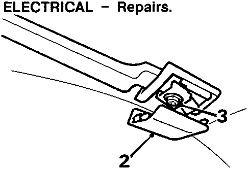
- Remove covers from grab handle fixings.
- Unscrew but do not remove 2 screws from each handle and remove grab handles.
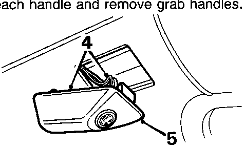
- Release ultrasonic sensor from L.H. rear quarter upper trim panel.
- Disconnect multiplug and remove sensor.
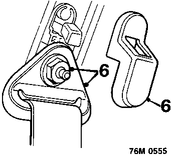
- Remove cover from L.H. upper seat belt anchorage, remove nut and release belt from anchorage.
Parts & tools for this job For Rover Coupé, Cabriolet & Tourer
- TOOLTrim removal tool kitSearch: trim removal tool kit
- PARTTouch-up paintSearch: Rover touch up paint
- PARTPanel clip assortmentSearch: Rover panel clips assortment
Links open Amazon search results in a new tab. As an Amazon Associate I earn from qualifying purchases.