
Remove
- Make
- Rover
- Model
- Coupé, Cabriolet & Tourer 200/400 Coupé, Cabriolet & Tourer Workshop Manual
- Section
- Interior trim components › Remove
BodyRemove
Service Repair No. 76.25.04
Remove
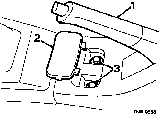
- Apply handbrake.
- Remove access cover.
- Remove 2 screws securing front end of console.
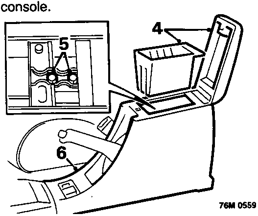
- Raise lid and remove cassette holder.
- Remove 2 screws securing rear end of console to bracket.
- Pull high console rearwards and up to release from beneath rear bracket and front console.
- Remove high console assembly.
Do not carry out further dismantling if component is removed for access only
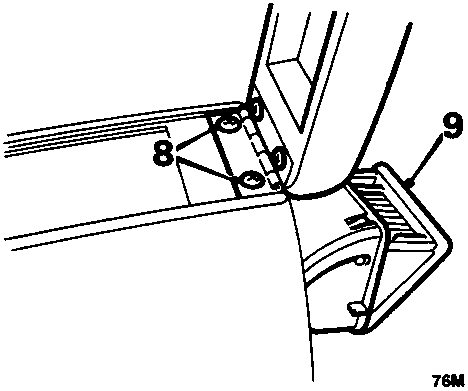
- Remove 2 screws and remove cassette lid.
- Open ashtray and remove ashtray assembly.
- Transfer components to new high console.
Refit
- Position high console over handbrake lever, lower into position and locate to front console and rear bracket.
- Fit screws, securing console.
- Fit cassette holder.
- Fit access cover.
Parts & tools for this job For Rover Coupé, Cabriolet & Tourer
- TOOLTrim removal tool kitSearch: trim removal tool kit
- PARTTouch-up paintSearch: Rover touch up paint
- PARTPanel clip assortmentSearch: Rover panel clips assortment
Links open Amazon search results in a new tab. As an Amazon Associate I earn from qualifying purchases.