
All engines (page 4 of 5)
- Make
- Rover
- Model
- 200 Workshop Manual
- Year
- 1995–1999
- Section
- Repairs
Engine - K16All engines · page 4 of 5
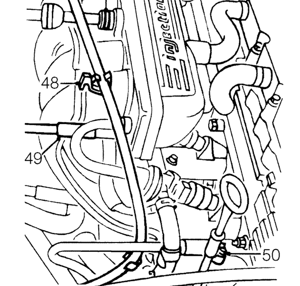
- Depress plastic collar on quick release connector and disconnect brake servo vacuum hose from inlet manifold.
- Release throttle cable from clip on inlet manifold.
- Disconnect vacuum hose from inlet manifold.
- Loosen clip and disconnect expansion tank hose from inlet manifold.
- Remove camshaft cover. See this section.
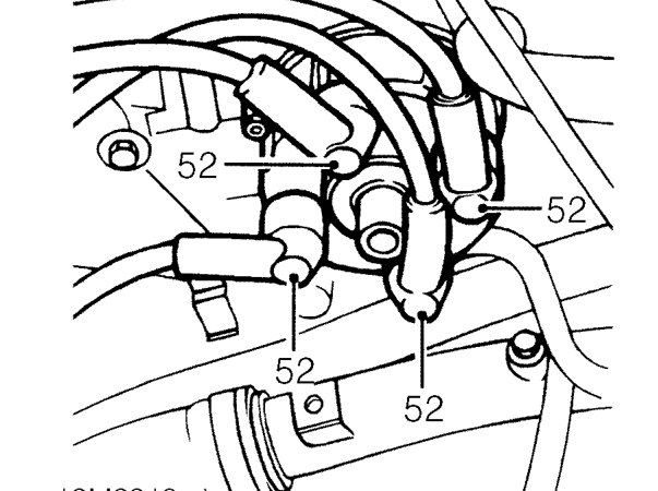
- Disconnect h.t. leads from distributor cap.
- Remove h.t. leads.
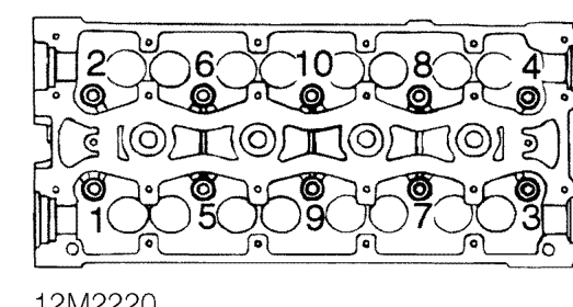
- Working in the sequence shown, loosen 10 cylinder head to oil rail bolts.
- Remove cylinder head bolts and store in fitted order.
- Using assistance, remove cylinder head assembly from cylinder block.
CAUTION: Take care not to damage HO2S when removing cylinder head.
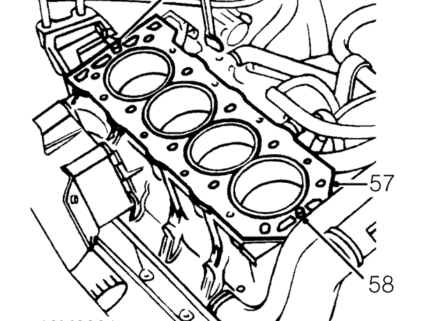
- Remove and discard cylinder head gasket from cylinder block.
- Remove 2 location dowels from cylinder block.
Parts & tools for this job For 1995 Rover 200
- PARTEngine gasket setSearch: Rover 200 1995 engine gasket set
- TOOLTorque wrenchSearch: 3/8 inch torque wrench
- TOOLFeeler gauge setSearch: feeler gauge set
Links open Amazon search results in a new tab. As an Amazon Associate I earn from qualifying purchases.