
Front side outriggers (page 2 of 2)
- Make
- Rover
- Model
- 400 Body Repair Manual
- Year
- 1995–2000
- Section
- Repairs
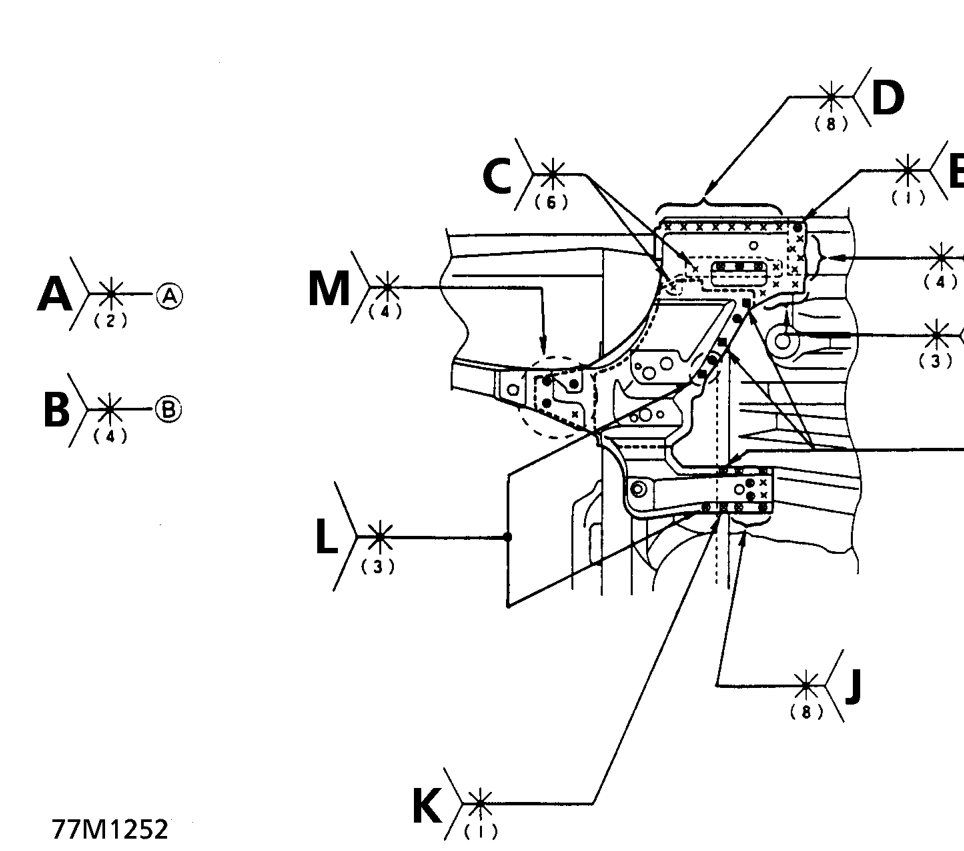
A. Front side outrigger, Dashboard lower and Dashboard lower insulator panel B. Front side outrigger, Dashboard lower and Dashboard lower cross member C. Front side outrigger and inside sill extension (include 3 points of 3-plate welding) D. Front side outrigger and Outer panel E. Front side outrigger, Inside sill and Outer panel F. Front side outrigger and Inside sill G. Front side outrigger and Front floor H. Front side outrigger, Dashboard lower and Front floor (include 2 points of 4-plate welding) J. Front side outrigger, Front centre floor and Front floor (include 2 points of 2-plate welding) K. Front side outrigger, Dashboard lower, Front centre floor and Front floor (4-plate welding) L. Front side outrigger, Dashboard lower and Dashboard lower cross member (include 1 point of 4- plate welding) M. Front side outrigger and Front side frame
Parts & tools for this job For 1995 Rover 400
- TOOLTorque wrenchSearch: 3/8 inch torque wrench
- TOOLSocket setSearch: socket set metric
- BOOKHaynes manualSearch: Haynes manual Rover 400
Links open Amazon search results in a new tab. As an Amazon Associate I earn from qualifying purchases.