
Replacement (page 2 of 4)
- Make
- Rover
- Model
- 400 Body Repair Manual
- Year
- 1995–2000
- Section
- Repairs
Panel repairsReplacement · page 2 of 4
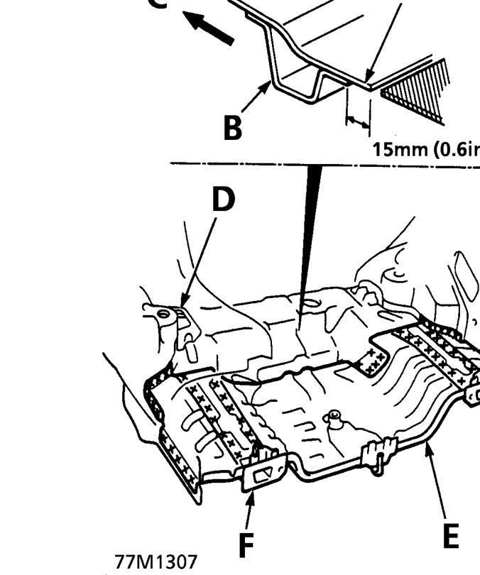
A. Rear Floor B. Rear Floor Cross Member C. Forward D. Rear Floor Stiffener E. Rear Floor F. Rear Frame
- Centre punch around the spot weld imprints on the remaining welded flanges. Do the same with the rear inner wing and the side of the rear end inner panel.
- Drill holes with a spot cutter.
NOTE: When drilling holes, be careful not to drill down to the rear frame.
- Prise off the flanges using a chisel.
- Mould the related parts.
- Remove the burrs from the spot weld or MIG weld using a sander.
WARNING: To prevent eye injury, wear goggles or safety glasses whenever sanding, cutting or grinding.
- Fill any holes made in the spot welded areas of the flange by MIG or gas welding.
WARNING: To prevent eye injury and burns when welding, wear an approved welding helmet, gloves and safety shoes.
- Smooth the welding flanges of the rear frame with a hammer and dolly.
NOTE: Check that the rear frames are parallel at the right and left.
• If necessary, remove the rear frame B from the rear frame A.
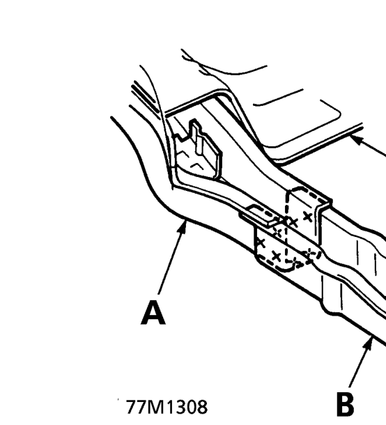
A. Rear Frame A B. Rear Frame B C. Rear Floor
- Keep the body level. Jack up the body at the front and back. Place safety stands at the four designated places of the side sill.
Parts & tools for this job For 1995 Rover 400
- TOOLTorque wrenchSearch: 3/8 inch torque wrench
- TOOLSocket setSearch: socket set metric
- BOOKHaynes manualSearch: Haynes manual Rover 400
Links open Amazon search results in a new tab. As an Amazon Associate I earn from qualifying purchases.