
Single cylinder head - r.r. and replace gasket
- Make
- Fiat
- Model
- Bravo Factory Service Manual
- Year
- 2007–2014
- Section
- Cylinder head/s › Single cylinder head - r.r. and replace gasket
SINGLE CYLINDER HEAD - R.R. AND REPLACE GASKET
Removing
Op. 1048A32 HOSE FROM AIR FILTER TO INTAKE MANIFOLD - R + R
Op. 1048A10 AIR FILTER ASSEMBLY - R.R.
Op. 1056B60 SINGLE FUEL MANIFOLD PIPE, WITH INJECTORS - R.R.
Op. 5520B10 STARTER MOTOR - R+R
Op. 1072B50 AIR CHAMBER - R.R.
Op. 1016B12 SINGLE CAMSHAFT HOUSING - R.R. WITH TIMING BELT REMOVED - REPLACE GASKET
Op. 1072C44 EXHAUST MANIFOLD HEAT SHIELD - R+R
Op. 1072C16 EXHAUST MANIFOLD WITH CATALYTIC CONVERTER - R.R.
Op. 0010T20 ENGINE COOLANT - CHANGE
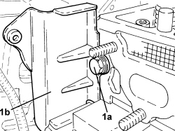
1. Undo the bolt (1a) and remove the timing belt inner guard (1b).
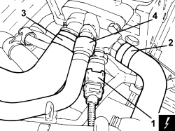
1. Disconnect the electrical connection for the coolant temperature sensor.
| Description | Connector | |
|---|---|---|
| 1 | Engine coolant temperature sensor/sender unit | See K036 ENGINE COOLANT TEMPERATURE SENSOR/SENDER UNIT |
2. Loosen the band and disconnect the engine coolant supply pipe to the heater, thermostat side.
3. Loosen the band and disconnect the radiator coolant supply hose, thermostat side.
4. Disconnect the degassing pipe rapid connector from the thermostat.
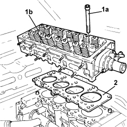
1. Undo the bolts (1a) and remove the cylinder head (1b).
2. Remove the cylinder head gasket.
Refitting
- Fit a new left cylinder head gasket on the cylinder block.
- Position the cylinder head on the crankcase by aligning the locating pins.
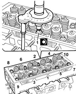
1. Tighten the bolts securing the cylinder head to the recommended torque.
Follow the order shown in the diagram for each tightening sequence.
| Component | Fastening | dia | Value (daNm) | Validity |
|---|---|---|---|---|
| Cylinder head | Bolt | M9 | 3 + 90° + 90° | 1.4 16v |
- Connect the degassing pipe rapid connector to the thermostat.
- Connect the radiator engine coolant supply hose, thermostat side, and secure it using the band.
- Connect the engine coolant supply pipe to the heater, thermostat side, and secure it using the band.
- Connect the electrical connection for the coolant temperature sensor.
- Place the timing belt inner guard in its housing and secure it using the bolt.
Op. 1072C16 EXHAUST MANIFOLD WITH CATALYTIC CONVERTER - R.R.
Op. 1072C44 EXHAUST MANIFOLD HEAT SHIELD - R+R
Op. 1016B12 SINGLE CAMSHAFT HOUSING - R.R. WITH TIMING BELT REMOVED - REPLACE GASKET
Op. 1072B50 AIR CHAMBER - R.R.
Op. 5520B10 STARTER MOTOR - R+R
Op. 1056B60 SINGLE FUEL MANIFOLD PIPE, WITH INJECTORS - R.R.
Op. 1048A10 AIR FILTER ASSEMBLY - R.R.
Op. 1048A32 HOSE FROM AIR FILTER TO INTAKE MANIFOLD - R + R
Op. 0010T20 ENGINE COOLANT - CHANGE
Removing
Op. 4450B12 FRONT WHEELS (TWO) - R+R
Op. 1016A10 SOUND-PROOFING COVER - R.R
Op. 7055B54 UNDER ENGINE PROTECTION/GUARD - R.R.
Op. 0010T20 ENGINE COOLANT - CHANGE
Op. 7055B65 ENGINE COMPARTMENT DUST COVER IN LEFT FRONT WHEEL ARCH - R.R.
Op. 7055B66 ENGINE COMPARTMENT DUST COVER IN RIGHT FRONT WHEEL ARCH - R.R.
Op. 1092G10 SINGLE ENGINE BELT - R.R
Op. 1092A10 CRANKSHAFT PULLEY - R + R
Op. 1092G14 ENGINE COMPONENT SINGLE BELT MOVING TENSIONER - R + R
Op. 1092G20 ENGINE COMPONENT SINGLE BELT FIXED TENSIONER - R + R
Op. 1032D12 TIMING SYSTEM PROTECTIVE COVER(S) - R + R
Op. 1032B10 TOOTHED TIMING BELT - R + R FOR TIMING ADJUSTMENT OR REPLACEMENT
Op. 1060F36 PIPES (ALL) FROM FUEL MANIFOLD TO INJECTOR - R.R.
Op. 1060F10 FUEL INJECTORS - R.R.
Op. 1060F20 PIPE FROM PRESSURE PUMP TO FUEL MANIFOLD - R.R.
Op. 1060F52 FUEL RETURN PIPE FROM INJECTORS - R.R.
Op. 1060F30 SINGLE FUEL MANIFOLD PIPE - R.R.
Op. 1016B10 SINGLE CAMSHAFT HOUSING - REPLACE GASKET
Op. 1036H55 HYDRAULIC TAPPET (ONE) - REPLACE WITH CAMSHAFT HOUSING REMOVED
Op. 1076B20 REAR EXHAUST SILENCER - R + R
- For versions without DPF only:
Op. 1080B62 CATALYTIC CONVERTER - R + R
- For versions with DPF only:
Op. 1080B81 PARTICULATE FILTER (D.P.F.) - R.R.
Op. 1076B72 INTERMEDIATE EXHAUST PIPE WITH HOSE SECTION - R+R
Op. 1072C44 EXHAUST MANIFOLD HEAT SHIELD - R+R
Op. 1048A41 HOSE FROM FLOW METER TO TURBOCHARGER - R.R.
Op. 1080C83 EXHAUST GAS INLET PIPING FROM EXHAUST MANIFOLD TO HEAT EXCHANGER EGR - R R
Op. 1048B19 TURBOCHARGER AIR OUTLET HOSE -R.R.
Op. 1064A27 PIPE BETWEEN VACUUM RESERVOIR AND ACTUATOR CONTROL SOLENOID VALVE - R.R.
Op. 1048A10 AIR FILTER ASSEMBLY - R.R.
Op. 1048B27 RIGID PIPE FOR AIR INLET TO THROTTLE BODY - R R
Op. 1080C24 E.G.R. SYSTEM SOLENOID - R + R
Op. 1080D34 ENGINE OIL VAPOUR SEPARATOR - R + R
1. Loosen the band and disconnect the flexible coolant supply pipe to the engine oil heat exchanger, water pump return pipe side.
2. Loosen the band and disconnect the water outlet hose from the radiator, water pump return pipe side.
3. Loosen the band and disconnect the flexible coolant return pipe to the engine oil heat exchanger, water pump return pipe side.
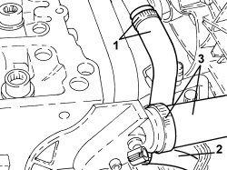
1. Loosen the band and disconnect the radiator coolant supply hose, thermostat side.
2. Loosen the band and disconnect the water return pipe to the heater, water pump rigid return pipe side.
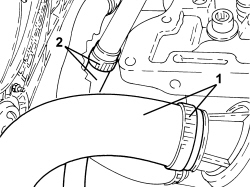
1. Loosen the band and disconnect the water supply pipe to the heater, thermostat side.
2. Disconnect the vacuum pipe from the throttle casing actuator.
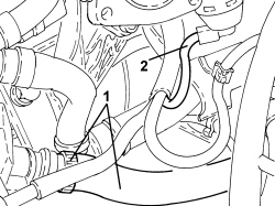
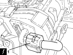
1. Detach the swirl actuator electrical connection.
| Description | Connector | |
|---|---|---|
| 1 | Flow modifier solenoid valve | See L064 FLOW MODIFYING SOLENOID VALVE |
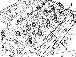
1. Undo the bolts fixing the cylinder head to the engine block.
2. Undo the bolt fixing the cylinder head to the pressure pump mount.
3. Remove the cylinder head.
- Remove the gasket.
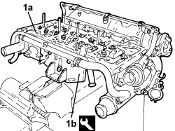
1. Position the cylinder head (1a) in a vice using the tool (1b).
| Tool | Description | Function | Validity |
|---|---|---|---|
| 1860470000 | Mount | Overhaul cylinder head |
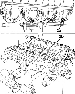
1. Loosen the band and disconnect the flexible degassing pipe from the rigid pipe.
2. Undo the nuts (2a) and remove the intake chamber assembly (2b).
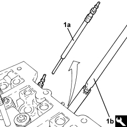
1. Undo the heater plugs (1a) and remove them using the special tool (1b).
| Tool | Description | Function | Validity |
|---|---|---|---|
| 2000003200 | Spanner | Removing/refitting glow heater plugs | 1.9 JTD 16v |
1. Loosen the band and disconnect the flexible supply pipe to the engine oil heat exchanger.
2. Undo the bolts (2a) and remove the water pump rigid return pipe (2b) complete with gasket.
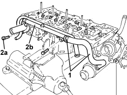
1. Loosen the band and disconnect the water supply pipe to the E.G.R. heat exchanger.
2. Undo the bolts (2a) and remove the thermostat (2b) complete with O-ring.
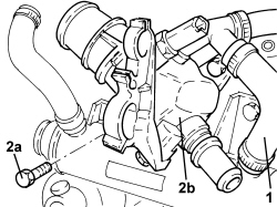
1. Undo bolts (1a) and remove exhaust gas heat exchanger assembly for the E.G.R. system (1b).
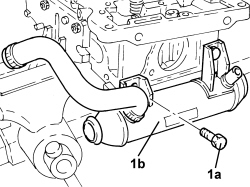
1. Undo the bolts (1a) and remove the coolant pump (1b) complete with gasket.
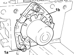
Refitting
- Clean any residues of the old gasket from the lower cylinder head plane.
- Check that the planarity of the lower cylinder head plane corresponds to the recommended values.
| Measurement | Value | Validity |
|---|---|---|
| Engine cylinder head lower surface flatness (mm) | < 0.1 |
- If the planarity of the lower cylinder head plane does not correspond to the recommended figures, regrind it without exceeding the minimum permitted height.
| Measurement | Value | Validity |
|---|---|---|
| Cylinder head lower plane minimum permitted height (mm) | 107 +/- 0.05 | 1.9 JTD 16v |
- Refit the water pump, complete with new gasket, in its housing and tighten the bolts to the recommended torque.
| Component | Fastening | dia | Value (daNm) | Validity |
|---|---|---|---|---|
| Water pump | Bolt | M8 | 2.3 ÷ 2.8 | 1.9 JTD |
- Place the exhaust gas heat exchanger for the E.G.R. system back in its housing and secure it by tightening the bolts to the specified torque.
| Component | Fastening | dia | Value (daNm) | Validity |
|---|---|---|---|---|
| E.G.R. exhaust gas heat exchanger | Bolt | M8 | 2.3 ÷ 2.8 | 1.9 JTD |
- Place the thermostat in its housing with the new O-ring and tighten the bolts to the recommended torque.
| Component | Fastening | dia | Value (daNm) | Validity |
|---|---|---|---|---|
| Thermostat | Bolt | M8 | 2.3 ÷ 2.8 | 1.9 JTD |
- Connect the water supply pipe to to the E.G.R. heat exchanger and tighten the band.
- Place the water pump rigid return pipe, complete with new gasket, in position and tighten the bolts.
- Connect the flexible water supply pipe to the engine oil heat exchanger and tighten the band.
- Refit the heater plugs using the tool and tighten them to the recommended torque.
| Component | Fastening | dia | Value (daNm) | Validity |
|---|---|---|---|---|
| Glow heater plug | M9 | 0.7 ÷ 0.9 | 1.9 JTD 16v |
| Tool | Description | Function | Validity |
|---|---|---|---|
| 2000003200 | Spanner | Removing/refitting glow heater plugs | 1.9 JTD 16v |
- Replace the intake chamber in its housing and secure it by tightening the nuts to the recommended torque.
| Component | Fastening | dia | Value (daNm) | Validity |
|---|---|---|---|---|
| Air chamber | Nut | M8 | 2.3 ÷ 2.8 | 1.9 JTD |
- Connect the flexible degassing pipe to the rigid pipe and tighten the band.
- Remove the cylinder head from the vice and from the tool.
1. Position the cylinder head locating bushes on the crankcase as shown in the figure.
The locating bushes between the crankcase and cylinder head are shorter (12.5 mm) than the bushes between the cylinder head and the camshaft housing (16.0 mm); take great care not to reverse them as this could impair engine operation.
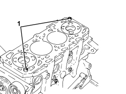
- Fit a new cylinder head gasket in position.
If the cylinder head has to be refaced, use a new cylinder head gasket that is the same size as the one removed. If the cylinder head required levelling, calculate the thickness of the new cylinder head to be used (see operation 1004E20).
Position the first cylinder at T.D.C.; rotate the crankshaft a further two teeth of the toothed timing drive pulley to lower the pistons thereby preventing any interference with the valves whilst fitting the cylinder head.
- Position the cylinder head on the crankcase.
Do not reuse the cylinder head bolts because they undergo permanent lengthening whenever they are tightened so they must be replaced.
1. Tighten the bolts securing the cylinder head to the recommended torque.
| Component | Fastening | dia | Value (daNm) | Validity |
|---|---|---|---|---|
| Cylinder head | Bolt | M12 | 6.2 ÷ 6.8 + 90° + 90° + 90° | 1.9 JTD |
Follow the order shown in the diagram for each tightening sequence.
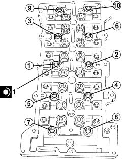
- Tighten the new bolt fixing the cylinder head to the pressure pump support to torque.
| Component | Fastening | dia | Value (daNm) | Validity |
|---|---|---|---|---|
| Pressure pump support | Bolt (to be replaced) | M8 | 2.3 ÷ 2.8 | 1.9 JTD |
- Connect the swirl actuator electrical connection.
- Connect the vacuum pipe to the throttle casing actuator.
- Connect the supply pipe to the heater, thermostat side and tighten the band.
- Connect the water return pipe to the heater, water pump rigid return pipe side and tighten the band.
- Connect the supply hose to the radiator, thermostat side, and tighten the band.
- Connect the flexible coolant return pipe to the engine oil heat exchanger, water pump return pipe side and tighten the band.
- Connect the water outlet hose to the radiator, water pump return pipe side and tighten the band.
- Connect the flexible coolant supply pipe to the engine oil heat exchanger, water pump return pipe side and tighten the band.
Op. 1080D34 ENGINE OIL VAPOUR SEPARATOR - R + R
Op. 1080C24 E.G.R. SYSTEM SOLENOID - R + R
Op. 1048B27 RIGID PIPE FOR AIR INLET TO THROTTLE BODY - R R
Op. 1048A10 AIR FILTER ASSEMBLY - R.R.
Op. 1064A27 PIPE BETWEEN VACUUM RESERVOIR AND ACTUATOR CONTROL SOLENOID VALVE - R.R.
Op. 1048B19 TURBOCHARGER AIR OUTLET HOSE -R.R.
Op. 1080C83 EXHAUST GAS INLET PIPING FROM EXHAUST MANIFOLD TO HEAT EXCHANGER EGR - R R
Op. 1048A41 HOSE FROM FLOW METER TO TURBOCHARGER - R.R.
Op. 1072C44 EXHAUST MANIFOLD HEAT SHIELD - R+R
Op. 1076B72 INTERMEDIATE EXHAUST PIPE WITH HOSE SECTION - R+R
- For versions with DPF only:
Op. 1080B81 PARTICULATE FILTER (D.P.F.) - R.R.
- For versions without DPF only:
Op. 1080B62 CATALYTIC CONVERTER - R + R
Op. 1076B20 REAR EXHAUST SILENCER - R + R
Op. 1036H55 HYDRAULIC TAPPET (ONE) - REPLACE WITH CAMSHAFT HOUSING REMOVED
Op. 1016B10 SINGLE CAMSHAFT HOUSING - REPLACE GASKET
Op. 1060F30 SINGLE FUEL MANIFOLD PIPE - R.R.
Op. 1060F52 FUEL RETURN PIPE FROM INJECTORS - R.R.
Op. 1060F20 PIPE FROM PRESSURE PUMP TO FUEL MANIFOLD - R.R.
Op. 1060F10 FUEL INJECTORS - R.R.
Op. 1060F36 PIPES (ALL) FROM FUEL MANIFOLD TO INJECTOR - R.R.
Op. 1032B10 TOOTHED TIMING BELT - R + R FOR TIMING ADJUSTMENT OR REPLACEMENT
Op. 1032D12 TIMING SYSTEM PROTECTIVE COVER(S) - R + R
Op. 1092G20 ENGINE COMPONENT SINGLE BELT FIXED TENSIONER - R + R
Op. 1092G14 ENGINE COMPONENT SINGLE BELT MOVING TENSIONER - R + R
Op. 1092A10 CRANKSHAFT PULLEY - R + R
Op. 1092G10 SINGLE ENGINE BELT - R.R
Op. 7055B66 ENGINE COMPARTMENT DUST COVER IN RIGHT FRONT WHEEL ARCH - R.R.
Op. 7055B65 ENGINE COMPARTMENT DUST COVER IN LEFT FRONT WHEEL ARCH - R.R.
Op. 0010T20 ENGINE COOLANT - CHANGE
Op. 7055B54 UNDER ENGINE PROTECTION/GUARD - R.R.
Op. 1016A10 SOUND-PROOFING COVER - R.R
Op. 4450B12 FRONT WHEELS (TWO) - R+R
Removing
Op. 4450B12 FRONT WHEELS (TWO) - R+R
Op. 7055B65 ENGINE COMPARTMENT DUST COVER IN LEFT FRONT WHEEL ARCH - R.R.
Op. 7055B66 ENGINE COMPARTMENT DUST COVER IN RIGHT FRONT WHEEL ARCH - R.R.
Op. 7055B54 UNDER ENGINE PROTECTION/GUARD - R.R.
Op. 0010T20 ENGINE COOLANT - CHANGE
Op. 1092G10 SINGLE ENGINE BELT - R.R
Op. 1016A10 SOUND-PROOFING COVER - R.R
Op. 1092A10 CRANKSHAFT PULLEY - R + R
Op. 1032D26 TIMING SYSTEM FRONT PROTECTIVE COVER (UPPER PART) - R.R.
Op. 1032D27 TIMING SYSTEM FRONT PROTECTIVE COVER (LOWER PART) - R.R.
Op. 1032B10 TOOTHED TIMING BELT - R + R FOR TIMING ADJUSTMENT OR REPLACEMENT
Op. 1060E30 PRESSURE PUMP DRIVE PULLEY - R.R.
Op. 1060F50 FUEL RETURN MANIFOLD - R.R.
Op. 1060E10 DIESEL INJECTION PRESSURE PUMP - R.R.
- Move the alternator away from the engine block with reference to
Op. 1044B10 FUEL FILTER ASSEMBLY - R + R OR REPLACE
Op. 1008B10 POWER UNIT FRONT SUPPORT FLEXIBLE MOUNTING (TIMING SIDE) - REPLACE
Op. 1060E40 PRESSURE PUMP SUPPORT - R.R.
Op. 1076B20 REAR EXHAUST SILENCER - R + R
- For versions with DPF only:
Op. 1080B81 PARTICULATE FILTER (D.P.F.) - R.R.
- For versions without DPF only:
Op. 1080B62 CATALYTIC CONVERTER - R + R
Op. 1076B72 INTERMEDIATE EXHAUST PIPE WITH HOSE SECTION - R+R
Op. 1072C44 EXHAUST MANIFOLD HEAT SHIELD - R+R
Op. 1048A41 HOSE FROM FLOW METER TO TURBOCHARGER - R.R.
Op. 1080C83 EXHAUST GAS INLET PIPING FROM EXHAUST MANIFOLD TO HEAT EXCHANGER EGR - R R
Op. 1048B19 TURBOCHARGER AIR OUTLET HOSE -R.R.
Op. 1064A27 PIPE BETWEEN VACUUM RESERVOIR AND ACTUATOR CONTROL SOLENOID VALVE - R.R.
Op. 1048A10 AIR FILTER ASSEMBLY - R.R.
Op. 1048B27 RIGID PIPE FOR AIR INLET TO THROTTLE BODY - R R
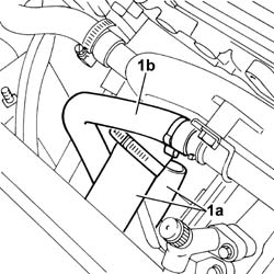
1. Disconnect the hoses (1a) from the water pump rigid water return pipe and the pipe (1b) from the heat exchanger rigid water pipe.
1. Disconnect the engine oil vapour recovery pipes (1a) and (1b) from the tappet cover.
2. Loosen the band and disconnect the vacuum pipe from the vacuum unit.
3. Loosen the band and disconnect the radiator coolant supply hose, thermostat side.
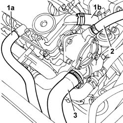
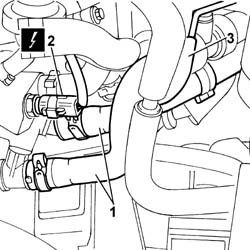
1. Disconnect the two heater coolant supply and return pipes from the thermostat.
2. Detach the electrical connection for the engine coolant temperature sensor.
| Description | Connector | |
|---|---|---|
| 2 | Engine coolant temperature sensor/sender unit | See K036 ENGINE COOLANT TEMPERATURE SENSOR/SENDER UNIT |
3. Disconnect the vacuum pipe for the vacuum reservoir, brake servo vacuum pipe side.
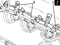
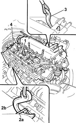
1. Disconnect the electrical connections for the injectors and open the wiring retaining clips.
| Description | Connector | |
|---|---|---|
| 1 | Injector | See N070 INJECTOR |
2. Undo the bolts fixing the wiring duct to the intake chamber.
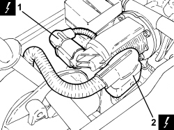
1. Disconnect the electrical connection for the E.G.R. solenoid valve.
| Description | Connector | |
|---|---|---|
| 1 | EGR solenoid valve | See L030 EGR SOLENOID VALVE |
2. Disconnect the electrical connection for the excess pressure sensor.
| Description | Connector | |
|---|---|---|
| 2 | Air pressure - temperature sensor | See K044 AIR TEMPERATURE/PRESSURE SENSOR |
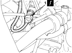
1. Detach the fuel pressure sensor electrical connection.
| Description | Connector | |
|---|---|---|
| 1 | Fuel pressure sensor | See K083 FUEL PRESSURE SENSOR |
1. Undo nut (1a), remove the glow plug preheating control unit (1b) and disconnect electrical connection (1c).
| Description | Connector | |
|---|---|---|
| 1 | Heater plugs control unit | See M015 PLUG PREHEATING CONTROL UNIT |
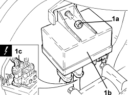
- Move the engine wiring aside.
1. Undo the bolts fixing the cam cover to the cylinder head.
2. Remove the tappet cover.
3. Undo the fixing bolts (3a) and remove the side timing belt guard (3b).
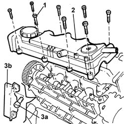
- Draw off the engine oil from the chambers in the cylinder head.
1. Loosen the bolts fixing the cylinder head.
2. Position a bracket (2a) to be connected to the hook (2b) for the removal of the cylinder.
3. Position a second hook on the intake manifold.
- Secure the chains to the hydraulic lift using the tool.
| Tool | Description | Function | Validity |
|---|---|---|---|
| 1871001700 | Balance | Removing/ refitting power unit |
4. Lift and remove the cylinder head, complete with intake manifold.
- Keep the cylinder head gasket from the cylinder block.
- To check the flatness of the lower cylinder head surface and grind if necessary, refer to
Op. 1016E10 SINGLE CYLINDER HEAD, REMOVED - OVERHAUL
Refitting
- Measure the projection of the pistons to select the correct size cylinder head gasket with reference to
- Place the cylinder head centering bushes on the cylinder block.
- Refit the new cylinder head gasket in its seat.
- Position the cylinder head on the cylinder block/crankcase.
- Remove the lifting tools.
1. Tighten the bolts fixing the cylinder head to the cylinder block to the recommended torque following the order illustrated.
| Component | Fastening | dia | Value (daNm) | Validity |
|---|---|---|---|---|
| Cylinder head | Bolt | M12 | 6.2 ÷ 6.8 + 90° + 90° + 90° | 1.9 JTD |
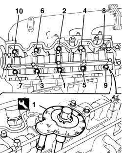
- Place the tappet cover in position on the cylinder head and secure it by tightening the bolts to the recommended torque.
| Component | Fastening | dia | Value (daNm) | Validity |
|---|---|---|---|---|
| Tappet cover | Bolt | M6 | 0.8 ÷ 1.0 |
- Position the engine wiring and secure it to the intake manifold tightening the fixing bolts.
- Connect the electrical connection to the heater plugs control unit.
- Place the heater plugs control unit in position and tighten the nut.
- Connect the electrical connection for the excess pressure sensor.
- Connect the electrical connection for the E.G.R. solenoid valve.
- Secure the electrical connection for the fuel pressure sensor.
- Secure the electrical connections for the injectors.
- Connect the vacuum pipe for the vacuum reservoir, brake servo vacuum pipe side.
- Connect the electrical connection for the engine coolant temperature sensor.
- Connect the two supply and return pipes to the heater, thermostat side.
- Connect the radiator coolant supply hose, thermostat side, and tighten the band.
- Connect the vacuum pipe to the vacuum unit and tighten the band.
- Connect the two engine oil vapour recovery pipes to the tappet cover.
- Connect the return hoses from the radiator and engine oil heat exchanger to the water rigid return pipe.
- Connect the flexible pipe to the engine oil heat exchanger rigid water pipe and secure it using the band.
Op. 1048B27 RIGID PIPE FOR AIR INLET TO THROTTLE BODY - R R
Op. 1048A10 AIR FILTER ASSEMBLY - R.R.
Op. 1064A27 PIPE BETWEEN VACUUM RESERVOIR AND ACTUATOR CONTROL SOLENOID VALVE - R.R.
Op. 1048B19 TURBOCHARGER AIR OUTLET HOSE -R.R.
Op. 1080C83 EXHAUST GAS INLET PIPING FROM EXHAUST MANIFOLD TO HEAT EXCHANGER EGR - R R
Op. 1048A41 HOSE FROM FLOW METER TO TURBOCHARGER - R.R.
Op. 1072C44 EXHAUST MANIFOLD HEAT SHIELD - R+R
Op. 1076B72 INTERMEDIATE EXHAUST PIPE WITH HOSE SECTION - R+R
- For versions without DPF only:
Op. 1080B62 CATALYTIC CONVERTER - R + R
- For versions with DPF only:
Op. 1080B81 PARTICULATE FILTER (D.P.F.) - R.R.
Op. 1076B20 REAR EXHAUST SILENCER - R + R
Op. 1060E40 PRESSURE PUMP SUPPORT - R.R.
Op. 1008B10 POWER UNIT FRONT SUPPORT FLEXIBLE MOUNTING (TIMING SIDE) - REPLACE
Op. 1044B10 FUEL FILTER ASSEMBLY - R + R OR REPLACE
- Place the alternator in position and secure it to the mounting with reference to
Op. 1060E10 DIESEL INJECTION PRESSURE PUMP - R.R.
Op. 1060F50 FUEL RETURN MANIFOLD - R.R.
Op. 1060E30 PRESSURE PUMP DRIVE PULLEY - R.R.
Op. 1032B10 TOOTHED TIMING BELT - R + R FOR TIMING ADJUSTMENT OR REPLACEMENT
Op. 1032D27 TIMING SYSTEM FRONT PROTECTIVE COVER (LOWER PART) - R.R.
Op. 1032D26 TIMING SYSTEM FRONT PROTECTIVE COVER (UPPER PART) - R.R.
Op. 1092A10 CRANKSHAFT PULLEY - R + R
Op. 1092G10 SINGLE ENGINE BELT - R.R
Op. 7055B54 UNDER ENGINE PROTECTION/GUARD - R.R.
Op. 7055B66 ENGINE COMPARTMENT DUST COVER IN RIGHT FRONT WHEEL ARCH - R.R.
Op. 7055B65 ENGINE COMPARTMENT DUST COVER IN LEFT FRONT WHEEL ARCH - R.R.
Op. 4450B12 FRONT WHEELS (TWO) - R+R
Op. 0010T20 ENGINE COOLANT - CHANGE
Op. 1016A10 SOUND-PROOFING COVER - R.R
Removing
- Position the vehicle on a lift.
Op. 7055B54 UNDER ENGINE PROTECTION/GUARD - R.R.
Op. 0010T20 ENGINE COOLANT - CHANGE
Op. 1016A10 SOUND-PROOFING COVER - R.R
Op. 1056B65 SOUND INSULATING COVER FOR INJECTOR ASSEMBLY - R.R.
Op. 1064A31 HEAT SHIELD FOR TURBOCHARGER - R.R.
Op. 1076A48 CATALYTIC CONVERTER HEAT SHIELD - R.R
Op. 1080B62 CATALYTIC CONVERTER - R + R
Op. 1084C22 HEAT SHIELD ON ENGINE OIL HEAT EXCHANGER - R.R.
Op. 1048A50 TURBOCHARGER AIR INTAKE PIPE - R.R.
Op. 1092G10 SINGLE ENGINE BELT - R.R
Op. 1092A10 CRANKSHAFT PULLEY - R + R
Op. 1032D26 TIMING SYSTEM FRONT PROTECTIVE COVER (UPPER PART) - R.R.
Op. 1032D27 TIMING SYSTEM FRONT PROTECTIVE COVER (LOWER PART) - R.R.
Op. 1084B40 ENGINE OIL DELIVERY PIPE TO TURBOCHARGER - R + R
Op. 1084B42 ENGINE OIL RETURN PIPE FROM TURBO - R + R
Op. 1088D48 PIPE FROM ENGINE COOLANT RESERVOIR TO TURBOCHARGER - R.R.
Op. 1088D50 ENGINE COOLANT OUTLET PIPE FROM TURBOCHARGER - R.R.
Op. 1072C44 EXHAUST MANIFOLD HEAT SHIELD - R+R
Op. 1064A27 PIPE BETWEEN VACUUM RESERVOIR AND ACTUATOR CONTROL SOLENOID VALVE - R.R.
Op. 1008B10 POWER UNIT FRONT SUPPORT FLEXIBLE MOUNTING (TIMING SIDE) - REPLACE
Op. 1008A46 POWER UNIT RIGID SUPPORT - TIMING SIDE - R.R.
Op. 5510C14 IGNITION COIL/S - R.R.
Op. 1072B53 AIR CHAMBER REINFORCEMENT BRACKET - R.R.
Op. 1080D34 ENGINE OIL VAPOUR SEPARATOR - R + R
Op. 1048B58 TURBOCHARGER AIR BY-PASS VALVE - R.R.
Op. 1032B10 TOOTHED TIMING BELT - R + R FOR TIMING ADJUSTMENT OR REPLACEMENT
Op. 1016B12 SINGLE CAMSHAFT HOUSING - R.R. WITH TIMING BELT REMOVED - REPLACE GASKET
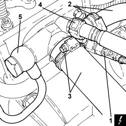
1. Undo bolt (1a) and remove timing belt inner guard (1b).
1. Disconnect the electrical connection for the engine coolant temperature sensor.
| Description | Connector | |
|---|---|---|
| 3 | Engine coolant temperature sensor/sender unit | See K036 ENGINE COOLANT TEMPERATURE SENSOR/SENDER UNIT |
2. Loosen the band and disconnect the engine coolant supply pipe to the heater, thermostat side.
3. Loosen the band and disconnect the radiator coolant supply hose, thermostat side.
4. Disconnect the degassing pipe quick coupling from the thermostat.
5. Disconnect the connector for the coolant supply pipe to the engine oil heat exchanger, thermostat side.
1. Undo bolts (1a) and remove cylinder head (1b).
2. Remove the cylinder head gasket.
Refitting
- Fit a new cylinder head gasket on the cylinder block.
- Position the cylinder head on the crankcase by aligning the locating dowels.
1. Tighten the bolts securing the cylinder head to the recommended torque.
Follow the order shown in the diagram for each tightening sequence.
| Component | Fastening | dia | Value (daNm) | Validity |
|---|---|---|---|---|
| Cylinder head | Bolt | M9 | 3 + 90° + 90° | 1.4 16v |
- Connect the connector for the coolant supply pipe to the engine oil heat exchanger, thermostat side.
- Connect the degassing pipe quick coupling to the thermostat.
- Connect the engine coolant supply hose to the radiator, thermostat side, and secure it using the band.
- Connect the engine coolant supply pipe to the heater, thermostat side, and secure it using the band.
- Connect the electrical connection for the engine coolant temperature sensor.
- Place the timing belt inner guard in its housing and secure it using the bolt.
Op. 1016B12 SINGLE CAMSHAFT HOUSING - R.R. WITH TIMING BELT REMOVED - REPLACE GASKET
Op. 1032B10 TOOTHED TIMING BELT - R + R FOR TIMING ADJUSTMENT OR REPLACEMENT
Op. 1048B58 TURBOCHARGER AIR BY-PASS VALVE - R.R.
Op. 1080D34 ENGINE OIL VAPOUR SEPARATOR - R + R
Op. 1072B53 AIR CHAMBER REINFORCEMENT BRACKET - R.R.
Op. 5510C14 IGNITION COIL/S - R.R.
Op. 1008A46 POWER UNIT RIGID SUPPORT - TIMING SIDE - R.R.
Op. 1008B10 POWER UNIT FRONT SUPPORT FLEXIBLE MOUNTING (TIMING SIDE) - REPLACE
Op. 1064A27 PIPE BETWEEN VACUUM RESERVOIR AND ACTUATOR CONTROL SOLENOID VALVE - R.R.
Op. 1072C44 EXHAUST MANIFOLD HEAT SHIELD - R+R
Op. 1088D50 ENGINE COOLANT OUTLET PIPE FROM TURBOCHARGER - R.R.
Op. 1088D48 PIPE FROM ENGINE COOLANT RESERVOIR TO TURBOCHARGER - R.R.
Op. 1084B42 ENGINE OIL RETURN PIPE FROM TURBO - R + R
Op. 1084B40 ENGINE OIL DELIVERY PIPE TO TURBOCHARGER - R + R
Op. 1032D27 TIMING SYSTEM FRONT PROTECTIVE COVER (LOWER PART) - R.R.
Op. 1032D26 TIMING SYSTEM FRONT PROTECTIVE COVER (UPPER PART) - R.R.
Op. 1092A10 CRANKSHAFT PULLEY - R + R
Op. 1092G10 SINGLE ENGINE BELT - R.R
Op. 1048A50 TURBOCHARGER AIR INTAKE PIPE - R.R.
Op. 1084C22 HEAT SHIELD ON ENGINE OIL HEAT EXCHANGER - R.R.
Op. 1080B62 CATALYTIC CONVERTER - R + R
Op. 1076A48 CATALYTIC CONVERTER HEAT SHIELD - R.R
Op. 1064A31 HEAT SHIELD FOR TURBOCHARGER - R.R.
Op. 1056B65 SOUND INSULATING COVER FOR INJECTOR ASSEMBLY - R.R.
Op. 1016A10 SOUND-PROOFING COVER - R.R
Op. 0010T11 ENGINE OIL - CHECK LEVEL AND TOP UP, IF NECESSARY
Op. 0010T20 ENGINE COOLANT - CHANGE
Op. 7055B54 UNDER ENGINE PROTECTION/GUARD - R.R.
- Remove the vehicle from the lift.
Parts & tools for this job For 2007 Fiat Bravo
- PARTEngine gasket setSearch: Fiat Bravo 2007 engine gasket set
- TOOLTorque wrenchSearch: 3/8 inch torque wrench
- TOOLFeeler gauge setSearch: feeler gauge set
Links open Amazon search results in a new tab. As an Amazon Associate I earn from qualifying purchases.