
1.4 and 1.6 models (page 2 of 3)
- Make
- Rover
- Model
- 400 Body Repair Manual
- Year
- 1995–2000
- Section
- Repairs
Panel repairs1.4 and 1.6 models · page 2 of 3
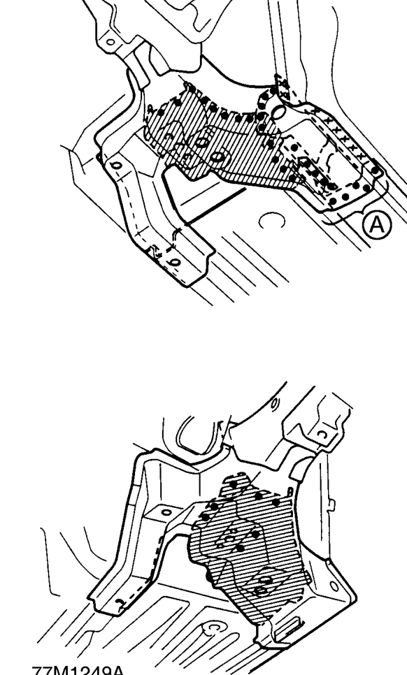
A. A Make 5 mm (0.2 in) holes in the MIG weld holes with the outrigger, and plug weld the inside sill with a MIG welder.
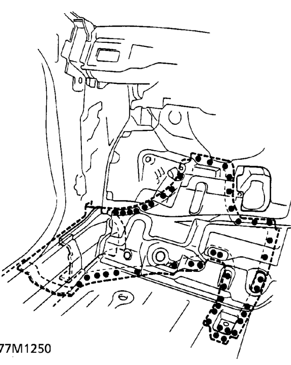
- From the passenger compartment side, plug weld the holed areas of the lower dashboard and front floor with a MIG welder.
- Finish the welded area. Use a hammer and dolly to even out the spring housing, inner wing, lower dashboard, front bulkhead and side sill flanges for a close fit with the surface of the front side frame.
- Apply sealer to the mating surfaces of the lower dashboard.
Parts & tools for this job For 1995 Rover 400
- TOOLTorque wrenchSearch: 3/8 inch torque wrench
- TOOLSocket setSearch: socket set metric
- BOOKHaynes manualSearch: Haynes manual Rover 400
Links open Amazon search results in a new tab. As an Amazon Associate I earn from qualifying purchases.