
Replacement (page 2 of 4)
- Make
- Rover
- Model
- 400 Body Repair Manual
- Year
- 1995–2000
- Section
- Repairs
Panel repairsReplacement · page 2 of 4
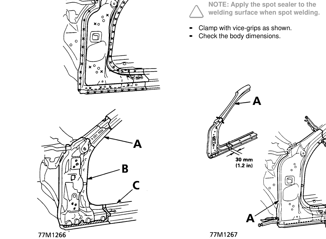
- Align the repair part with the top cut section, then cut it with a handsaw.
NOTE: Cut the side sill joint with a handsaw leaving an overlap of 30 mm (1.2 in).
- Remove the undercoat from both sides of the areas to be spot welded with a sander to expose the steel plate.
NOTE: Apply the spot sealer to the
welding surface when spot welding.
- Clamp with vice-grips as shown.
- Check the body dimensions.
A. Inner upper stiffener B. Front pillar stiffener C. Outer panel
- Mould the related parts. Fill any holes by MIG welding, and even out with a hammer and dolly.
WARNING: To prevent eye injury and burns when welding, wear an approved welding helmet, gloves and safety shoes.
- Set the repair part.
A. Repair Part
- Tack weld the clamped sections.
WARNING: To prevent eye injury and burns when welding, wear an approved welding helmet, gloves and safety shoes.
- Temporarily mount the door and front wing.
- Remove the vice-grips, then mount the door.
- Check the clearance and level differences of the door and wing.
Parts & tools for this job For 1995 Rover 400
- TOOLTorque wrenchSearch: 3/8 inch torque wrench
- TOOLSocket setSearch: socket set metric
- BOOKHaynes manualSearch: Haynes manual Rover 400
Links open Amazon search results in a new tab. As an Amazon Associate I earn from qualifying purchases.