Workshop Manuals Factory service & repair Rover
01 Information02 General data03 Engine04 Engine management system – PGM-Fi05 Cooling system, manifold and exhaust06 Clutch07 Manual gearbox08 Automatic gearbox09 Drive shafts10 Differential – manual gearbox11 Differential – automatic gearbox12 Steering13 Suspension14 Brakes and ABS15 Brakes – ABS BY416 Body17 Heating and ventilation18 Electrical19 Supplementary restraint system (SRS)
Rover Rover 600 Repair Manual - Volumes 1 and 2 - 2nd Edition08 · Automatic gearbox
08 · Transmission

Components

Make
Rover
Model
600 Rover 600 Repair Manual - Volumes 1 and 2 - 2nd Edition
Section
Repairs › Components
Automatic gearboxComponents

Components – diagram from the Automatic gearbox chapter of the Rover Rover 600 Repair Manual - Volumes 1 and 2 - 2nd Edition factory manual.

Components
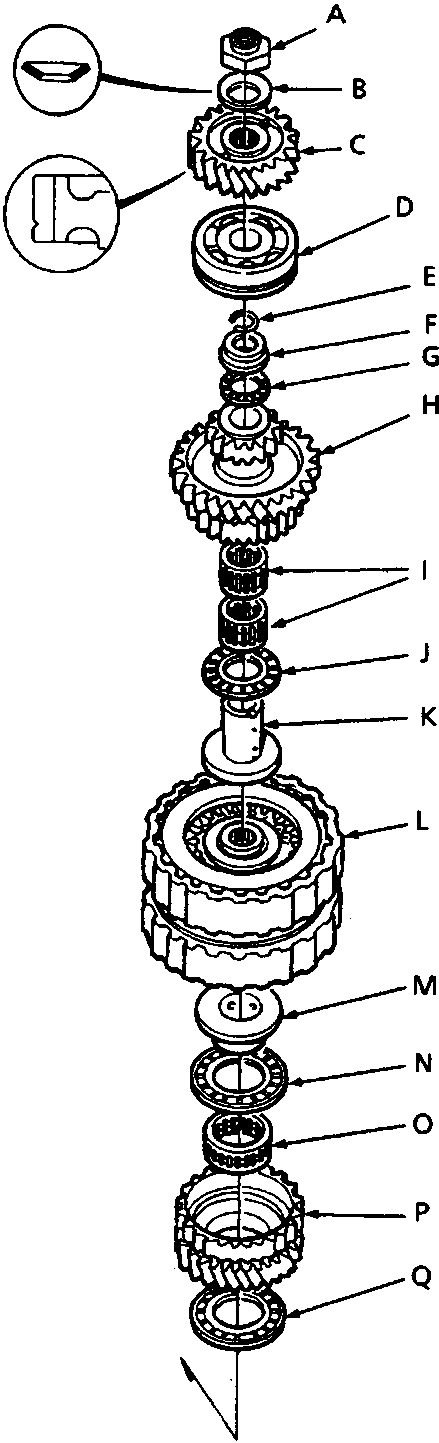
Exploded view of the mainshaft components showing parts labeled A through Q, including gears, bearings, washers, and retainers. Two circular insets show detailed cross-sections of specific components. The figure is identified as 44M 0438.
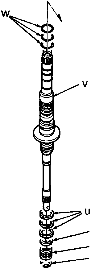
Continuation of the mainshaft assembly showing the lower section with parts labeled R through W, including thrust washers, a shaft, and retaining rings.

Parts & tools for this job For Rover 600

Links open Amazon search results in a new tab. As an Amazon Associate I earn from qualifying purchases.