
Test
- Make
- Rover
- Model
- 600 Rover 600 Repair Manual - Volumes 1 and 2 - 2nd Edition
- Section
- Repairs › Test
Automatic gearboxTest
Test
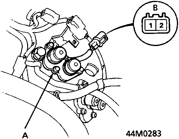
A Lock-up control solenoid valve assembly
B 2-P connector, View from terminal side
CAUTION: Lock-up control solenoid valves A and B must be replaced as an assembly.
- Disconnect lock-up control solenoid valve A and B harness connector from main harness.
- Measure resistance between the No. 1 terminal (solenoid valve A) of the lock-up control solenoid valve connector and body earth and between the No. 2 terminal (solenoid valve B) and body earth.
Data: Resistance = 14 to 16 ohms at 25°C
- Replace lock-up control solenoid valve assembly as necessary.
- If the resistance is as specified, connect the No. 1 terminal of the lock-up control solenoid valve connector to the battery positive terminal. A clicking sound should be heard. Connect the No. 2 terminal to the battery positive terminal. A clicking sound should be heard. Replace the lock-up control solenoid valve assembly if no clicking sound is heard.
Replacement
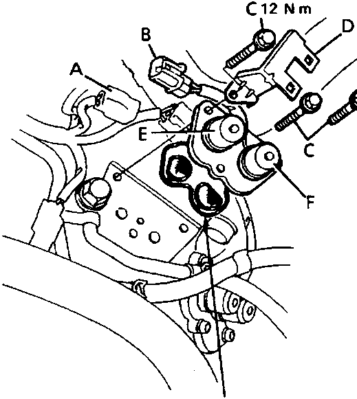
A Lock-up control solenoid valves A and B main harness connector
B Lock-up control solenoid valves A and B harness connector
C Securing bolts
D Harness connector securing bracket
E Lock-up control solenoid valve A
F Lock-up control solenoid valve B
G Combined filter/gasket
CAUTION: Lock-up control solenoid valves A and B must be replaced as an assembly.
- Disconnect lock-up control solenoid valve A and B harness connector from main harness.
- Release 2 main harness connectors from securing bracket.
- Remove 3 bolts securing lock-up control solenoid valve assembly, remove harness connector securing bracket.
- Remove lock-up control solenoid valves assembly, remove and discard combined filter/gasket.
- Clean the mounting surface and the oil passages of the lock-up control solenoid valve assembly, and install a new filter/gasket.
- Position lock-up control solenoid valve, fit and tighten bolts to 12 Nm.
- Check the connector for rust and contamination, clean if necessary and refit connector securely.
Parts & tools for this job For Rover 600
- PARTTransmission filter kitSearch: Rover 600 transmission filter kit
- FLUIDAutomatic transmission fluidSearch: Rover automatic transmission fluid
- TOOLFluid transfer pumpSearch: fluid transfer pump
Links open Amazon search results in a new tab. As an Amazon Associate I earn from qualifying purchases.